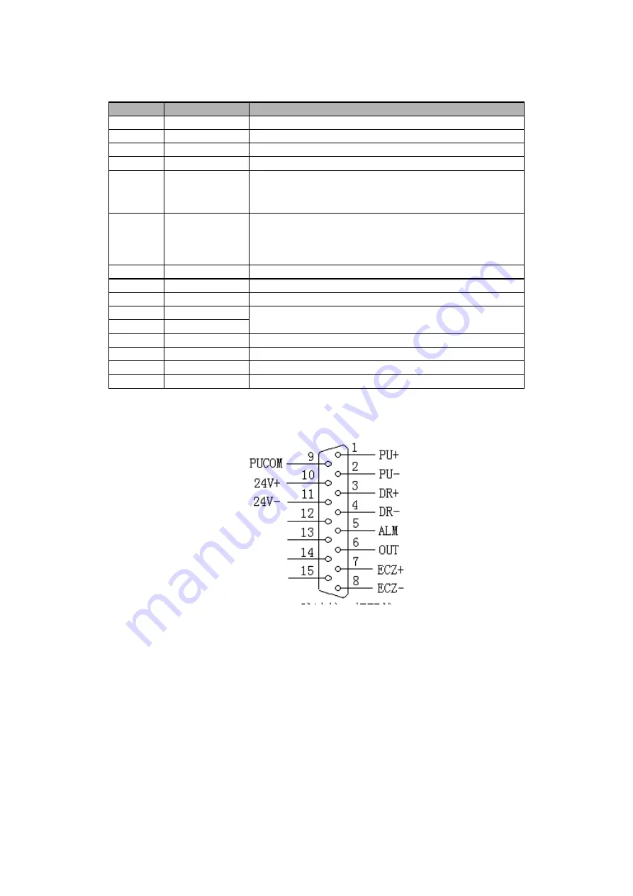
Line No.
Definition
Function
1
PU+
Pulse
2
PU-
Pulse signal -
3
DR+
Direction
4
DR-
Direction signal-
5
ALM
Servo alarm signal input
X axis: IN34
、
Y axis: IN35
、
Z axis: IN36
、
A axis: IN37
、
B axis: IN38
、
C axis: IN39
6
OUT
Axis alarm reset output signal
X axis: OUT18 Y axis: OUT19 Z axis: OUT20 A
axis:OUT21
B axis: OUT22 C axis: OUT23
7
ECZ+
Encoder Z phase input+
8
ECZ-
Encoder Z phase input-
9
PUCOM
Single input for driver
10
24V+
Internal 24V power supply and connected to 24V power of
controller
11
24V-
12
ECA+
Encoder A phase input
13
ECA-
Encoder A phase input -
14
ECB+
Encoder B phase input
15
ECB-
Encoder B phase input
Standard pulse wiring circuit diagram
Adapt to ADT-8860 controller
Stepper motor drive connection with the differential input drive for CNC
drives for reference, for all NC drive as differential input, strong
anti-jamming in this manner, recommended that you use this method. ADT
8860 between drives, stepper motors and stepper motor connection see
figure below


