background image

- P1 -

DL1


RS-485 Data Collection Recorder     < User Manual>

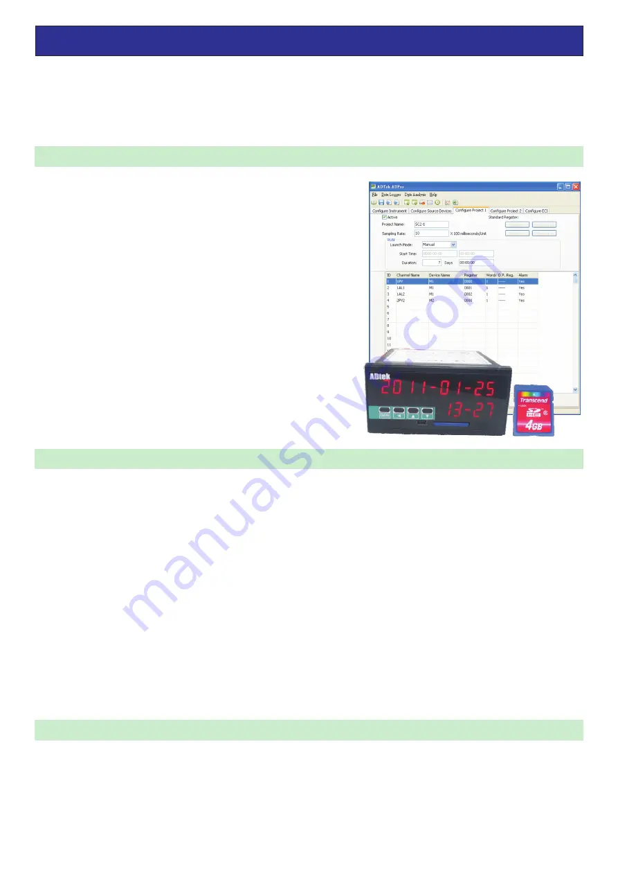
DL1 is


design


to communicate


through


RS485


to read variety of


devices

 (

Such


as


instrumentation

PLC

A

 / 

D


conversion


card

 . . . . ) 

and stored the data collected into a SD card 

.

Data


can then be converted 

to Excel


file


format


on a computer to perform analysis


and


production


of


related


reports


needed


by


users

.

This product


not


only


read


and record data speed up to 0.1 seconds, and 

its flexible software setting allows in many ways for easy


planning

For


multiple


projects


user

DL1


provide


two


project


planning


procedures


which


stored


the


data


into


two


separate


files

After


all


setting


on


software

parameter


can


be


upload

/

download


to


DL1


using


a


USB 

interface


cable

Recording


can


be


start


by


external


DI


contact


or


by


meter


button

.

®

ADPro  is the software provided with the hardware for setting parameters 
and procedures


planning


through the USB interface cable to the DL1.

Today there are


lots of field 

(

such


as


industrial

energy

environment


monitoring

commercial information ....),needs


record process data,


providing


DL1 is rather inexpensive solution compare to present industrial 

recorder. 

DL1 give


a


simple

convenient and economical solution


for


all

■ 產品 說 明

■ 特點

Features

Applications

Product Description

Communication and


display device

l

l

l

l

l

l

l

l

1 Group


RS485 Master


Communication


port

 (

Modbus


RTU


mode

) ,

connectfrom


(

standard

to 32


devices

.

The 

maximum


read


speed of


0.1 second

Circular


display window


showing the


document


reading position

and


information for users to understand the


recording 

status.

Two


external control


inputs


can be arbitrarily


set to


start recording or


frequency input

and


other


related


functions

Innovative


disk


installation

 ( 9 6 

x

 48 

mm

), 

installation depth


is only


120mm

suitable for installation in


a variety of 

devices


used


for long-term


record

Storage

1


Group


SD


card slot

you


can


use


2 ~ 32GB SDHC


card to store


the data

1 Group


USB


interface cable use


with


the


ADPro 

® 

software


uploading, downloading


configuration parameters


and 

updating


software

Input and output


control device

2


set of external


control input

(

E.C.I.)

 With the


external


contact control,


instrument


can


start


or stop


recording

Upper or


lower limits


can be set


out


warning


buzzer


to alert


operators to


abnormal conditions


in time

l

l

l

Production line


test equipment

data recording


system 

,

data


online


data collection,


quality control


of


portable


test 

equipment

data recording


devices


measured.

PLC


equipment


and abnormal


movements


of


program records

records


of


power consumption.

Records of


solar


power generation system


and efficiency


of


power generation.

Thank


you


for


purchasing


this


instrument

PLEASE


READ


MANUAL


before


operating


the


instrument

.

Safety Tips:

 Power


OFF


before


any


Installation


and


removal


of


the


instrument

 Do


not


use


under


direct


sunlight

 (

ambient


temperature


is -10 ~ +60 

)

 Be


sure


to


ground


the


instrument

 (

ground


resistance


<10 ohms

). 

Do


not


shared


same


ground


with


other


large


electrical


load

Ungrounded


or


faulty


grounding


may


lead


to


electric


shock

malfunction


and


other


faulty


conditions


occur

 The device uses single-phase AC power supply 85V ~ 264V.

&
&
&

&

Summary of Contents for DL1

Page 1: ...wing the document reading position and information for users to understand the recording status Two external control inputs can be arbitrarily set to start recording or frequency input and other related functions Innovative disk installation 96 x 48 mm installation depth is only 120mm suitable for installation in a variety of devices used for long term record Storage 1 Group SD card slot you can u...

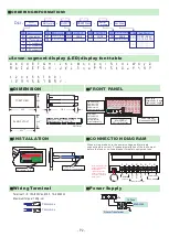
Page 2: ...reaker for safety equipment use 7 0mmmax 7 0mmmax Terminal 1 8 15A 600Vac M3 5 12 22AWG Maximum torque 13Kg cm Power Supply Wiring Terminal Filter or Transformer L N G L N G 1A Fuse AC85 264V 8 7 6 Note Please state the header transmission installation or replacement of the battery otherwise it will result in reduced battery life 01 06 Rs485 sub machine P1 Multi record Aux Power DL1 1 sub machine ...

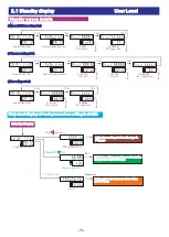
Page 3: ... display WAIT word sdCck no card no card no sd card no space space less sdc error SD Card Exception unformat SD card Unformatted no space sdc error D0 link er 48 ck D0 link er D0 link er 48 ck DnNlink er DnNlink er D03 LINK ER Device 03 link Error Press ENT key into SKIP CHECK Select and press ENT into the next error message Dnn LINK ER Device nn link Erro Press ENT key into SKIP CHECK Select and ...

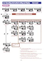
Page 4: ...our Min done proJ aaaaa P1 AAAAA Start button done proJ bbbbb P2 BBBBB ECITrigger Start Recording ended 1sec 1sec Standby Display Press ENT into 09 30 2010 11 20 Now Date Hour Min 0000 password Password Enter engineer level parameters setting go to P7 page Press ENT into S run aaaaa Started recording and enter record excution display screen go to P6 page Choose to start PROJ sdCmb 4000 mb Prass 1s...

Page 5: ...ing Flashing Flashing sTmd front key Start button 1 sTmd eci on ECI Control start smlPr 00 00 0 0 Sample rate 1 0 sec cRpin eci 1 Control Pin ECI 1 5 levl low ECI Action Level LOW To change the start mode press ENT into the Edit screen choose only one type PROJ 2 Setting same as PROJ 1 sTmd Start recording Start Mode If setting is done in ADPro software screen display start mode type same setting ...

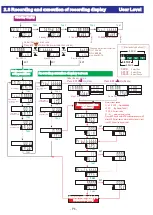
Page 6: ...aaaa Pause PROJ Choose bbbbb both aaaaa bbbbb both aaaaa Press ENT into Pause Under the any picture Choose a project which started PJ1 1 AAAAA PJ2 2 BBBBB or on time BOTH Standby display 1sec Recording excution display screen Flashing Flashing ENT FN S RUN S STOP S STOP S PAUS S RUN S STOP Select Stop S PAUS Pause Select Run Select al hi 199 9 Alarm screen when alert occur taG01 proJ aaaaa 1sec al...

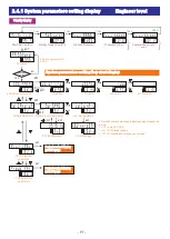
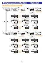
Page 7: ...meters 09 30 2010 11 20 Now Date Hour Min stand by 09 30 Standby Display Hour Min edkey proj aaaaa P1 AAAAA Start button Password 1sec 00 35 proj bbbbb P2 bbbbb Remaining 35 points 10 05 proj bbbbb P2 bbbbb 10 05 Start 1sec 1sec 1sec 1sec System parameters setting flow chart display PS Key in password set in ADPro Flashing Flashing Project content display go to P8 page ENT ENT Project content disp...

Page 8: ...Address none 0 aLl nN dnN0000 taGnN Upper limit alarm 25 00 nNaLh Lower limit alarm Command line Name Station Number Address 10 00 nNaLl edit name proJ2 para PROJ 2 Set the PROJ 2 Name ENT EXIT proJ bbbbb 01 first instruction d01 Header No 0000 Parameter address TAG01 tagname 0 d0 0000 tmP01 Upper limit alarm 25 00 0 aLh Lower limit alarm 01 02 nn Command line Name Station Number Address 250 00 If...

Reviews: