background image

- P2 -

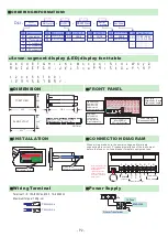
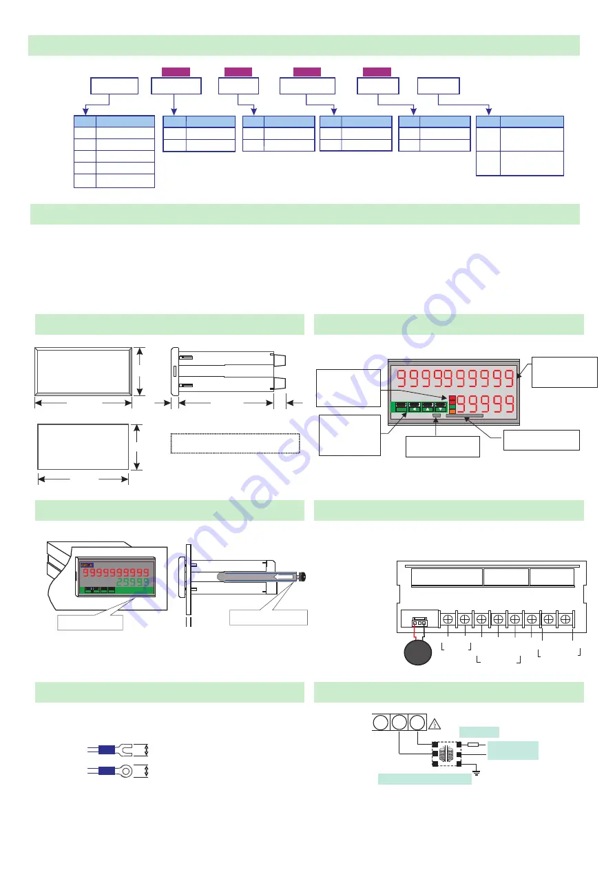
ORDERING


INFORMATIOM

A

b

C

d

E

F

G

H

i

J

K

L

M

a b c d e f g h i j k l m

n

o

p

q

r

S

t

U

v

W X

y

Z

n o p q r s t u v w x y z

1

2

3

4

5

6

7

8

9

/

.

1 2 3 4 5 6 7 8 9 / .

ENT/FN


LED status display
AL1:Alarm 1 LED
AL2:Alarm 2 LED
ECI:SD card LED
COM:Communication LED

Enter button
ENT/FN/ENTER
Left button/Left
Next/Increase key
Previous/Reduce key

SDHC card Slot

Max. support to 32G

Main Display
Upper display: 10 digital
Lower display: 5 digital

Mini USB Slot

ADPro for DownLoad

Seven-segment display (LED) display font table

FRONT


PANEL

DIMENSION


Unit: mm


Dimensions: 96(W) x 48(H) x 120(D)


48.0

FORNT VIEW

PANEL


CUT

-

OUT

+0.2

44.0

+0.2

92.0

96.0

100.0

8.0

12.0

+0.2

+0.2

Panel


Cutout

:

 92

(W) x 44

(H)

CONNECTION DIAGRAM

INSTALLATION


PANEL CUT-OUT:

+0.2

+0.2

92

(W)X44

(H) mm

FIX HOLDER:

104 mm(L) / 12mm(W) M3

When wiring, make sure the power voltage and terminals 
connection are correct. Proposed installation of the instrument 
before the fuse or no-fuse breaker for safety equipment use.


7.0mm max


7.0mm max


Terminal


1~8:


15A

/

600Vac, M3.5, 12~22AWG

Maximum torque

13Kg-cm

Power Supply

W iring Ter minal 

Filter or Transformer


N  

G  

N  

G  

1A

Fuse


AC85~264V


  8  

7

6

Note: Please state the 
header transmission 
installation or 
replacement of the 
battery, otherwise it 
will result in reduced 
battery life!!

01
06

Rs485 sub-machine

P1

Multi-record

Aux Power

DL1


1 sub-machine

~6 

1

sub-machine

12

~  

1 12 sub-machine

18

~  

1 18 sub-machine

32

~  

1 32 sub-machine

3 Group relays

Rs485

 sub-machine

AC 85~264V
DC 100~300V

AC 20~56V
DC 20~56V

ADH

ADL

Multi-record

 -  

 -  

8N

NONE

8S

RS485 Slave

OUTPUT

 -  

TN

NONE

T1

Ethernet Interface

 -  

Ethernet Interface

RS485 Slave

Optio n 1

Optio n 2

Optio n 3

P2

can be set 2 Program

CODE

CODE

CODE

CODE

CODE

 -  

RN

NONE

R3

CODE

Aux Power

 -  

Optio n 4

Ethernet

      Interface

OUTPUT

OUTPUT

Single-1 program

Note: The light-colored part of the specifications for the new version of the word book additional features, is currently temporarily unavailable

FG

D-

D+

AUX

.

POWER

Clock

Memory
 Battery

AC85~2

V

64

RS485

com.port

1

2

3

4

5

6

7

8

External


Control


Input

E

C

I-

1

E

C

I-

2

C

O

M

Summary of Contents for DL1

Page 1: ...wing the document reading position and information for users to understand the recording status Two external control inputs can be arbitrarily set to start recording or frequency input and other related functions Innovative disk installation 96 x 48 mm installation depth is only 120mm suitable for installation in a variety of devices used for long term record Storage 1 Group SD card slot you can u...

Page 2: ...reaker for safety equipment use 7 0mmmax 7 0mmmax Terminal 1 8 15A 600Vac M3 5 12 22AWG Maximum torque 13Kg cm Power Supply Wiring Terminal Filter or Transformer L N G L N G 1A Fuse AC85 264V 8 7 6 Note Please state the header transmission installation or replacement of the battery otherwise it will result in reduced battery life 01 06 Rs485 sub machine P1 Multi record Aux Power DL1 1 sub machine ...

Page 3: ... display WAIT word sdCck no card no card no sd card no space space less sdc error SD Card Exception unformat SD card Unformatted no space sdc error D0 link er 48 ck D0 link er D0 link er 48 ck DnNlink er DnNlink er D03 LINK ER Device 03 link Error Press ENT key into SKIP CHECK Select and press ENT into the next error message Dnn LINK ER Device nn link Erro Press ENT key into SKIP CHECK Select and ...

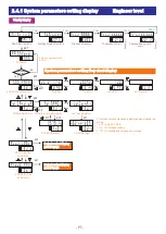
Page 4: ...our Min done proJ aaaaa P1 AAAAA Start button done proJ bbbbb P2 BBBBB ECITrigger Start Recording ended 1sec 1sec Standby Display Press ENT into 09 30 2010 11 20 Now Date Hour Min 0000 password Password Enter engineer level parameters setting go to P7 page Press ENT into S run aaaaa Started recording and enter record excution display screen go to P6 page Choose to start PROJ sdCmb 4000 mb Prass 1s...

Page 5: ...ing Flashing Flashing sTmd front key Start button 1 sTmd eci on ECI Control start smlPr 00 00 0 0 Sample rate 1 0 sec cRpin eci 1 Control Pin ECI 1 5 levl low ECI Action Level LOW To change the start mode press ENT into the Edit screen choose only one type PROJ 2 Setting same as PROJ 1 sTmd Start recording Start Mode If setting is done in ADPro software screen display start mode type same setting ...

Page 6: ...aaaa Pause PROJ Choose bbbbb both aaaaa bbbbb both aaaaa Press ENT into Pause Under the any picture Choose a project which started PJ1 1 AAAAA PJ2 2 BBBBB or on time BOTH Standby display 1sec Recording excution display screen Flashing Flashing ENT FN S RUN S STOP S STOP S PAUS S RUN S STOP Select Stop S PAUS Pause Select Run Select al hi 199 9 Alarm screen when alert occur taG01 proJ aaaaa 1sec al...

Page 7: ...meters 09 30 2010 11 20 Now Date Hour Min stand by 09 30 Standby Display Hour Min edkey proj aaaaa P1 AAAAA Start button Password 1sec 00 35 proj bbbbb P2 bbbbb Remaining 35 points 10 05 proj bbbbb P2 bbbbb 10 05 Start 1sec 1sec 1sec 1sec System parameters setting flow chart display PS Key in password set in ADPro Flashing Flashing Project content display go to P8 page ENT ENT Project content disp...

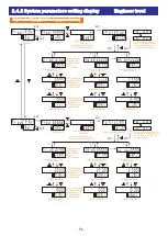
Page 8: ...Address none 0 aLl nN dnN0000 taGnN Upper limit alarm 25 00 nNaLh Lower limit alarm Command line Name Station Number Address 10 00 nNaLl edit name proJ2 para PROJ 2 Set the PROJ 2 Name ENT EXIT proJ bbbbb 01 first instruction d01 Header No 0000 Parameter address TAG01 tagname 0 d0 0000 tmP01 Upper limit alarm 25 00 0 aLh Lower limit alarm 01 02 nn Command line Name Station Number Address 250 00 If...

Reviews: