Total Access 3000 23-Inch Chassis Installation and Maintenance Practice
6
61181001L1-5E
POWER CONNECTIONS
The backplane contains all I/O connectors, control signal routing, and power routing, as well
as all necessary interconnections between access modules, the multiplexer cards and the
System Controller Unit (SCU). No wire wrapping for network or loop connections is necessary
for normal chassis operation. Additional wire-wrap terminals on the backplane accommodate
special modes, such as metallic loop testing and external alarm input. Detailed wiring
diagrams are provided later in this practice.
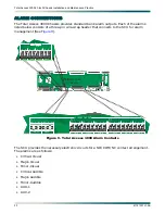
All permanent connections to Total Access 3000 Chassis are made on the backplane.
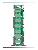
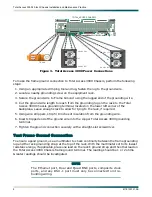
illustrates the backplane and
indicates the location of the power and ground connec-
tions.
Frame Ground Connection
The frame ground lug, located on the lower left corner of the backplane, can accommodate
from 8 to 14 AWG wire. When connecting the frame ground, use a wire gauge that is at least
as heavy as the power wiring.
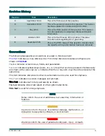
NOTE
The ground wire exiting the chassis must be terminated with a UL
Listed grounding lug. The grounding lug must be a two-hole lug or
a one-hole lug that is used in conjunction with an anti-rotation
device. The surface of the lug that connects to the frame shall be
cleaned and an antioxidant applied. The same shall be done for the
surface of the frame or bus where the connection is to be made. An
approved thread-forming screw shall be used to connect the frame
ground connector to the frame or bus.

