Total Access 3000 23-Inch Chassis Installation and Maintenance Practice
16
61181001L1-5E
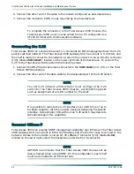
MUX B Clock Output (B-OUT) - P20
The MUX B clock output Used to output a DS1 BITS clock from a SONET MUX B. Wire the “
+
”,
“
–
” and drain lead from the connector P20 to the subsequent equipment’s “
+
”, “
–
” and drain
lead.
Wiring Test Access (T1 Only)
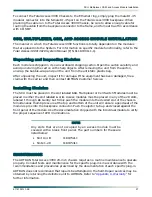
A six-lead (T, R, and drain, T1, R1, and drain) common test access bus (P13) is provided for
metallic test access to all customer loops and is labeled
LOOP TEST ACCESS
on the backplane.
An additional test access bus (P23), labeled
DSX1 TEST ACCESS
, allows for logical loop testing.
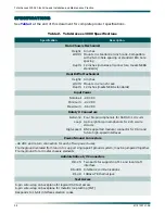
If the Total Access 3000 being installed will use these testing features, wiring will be required
to gain access to the test leads.
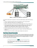
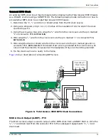
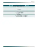
Connect Mechanical Loop Test (T1 Only)
Mechanical Loop Test (MLT) access is gained by wiring into the connector labeled
LOOP TEST
ACCESS
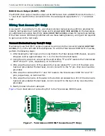
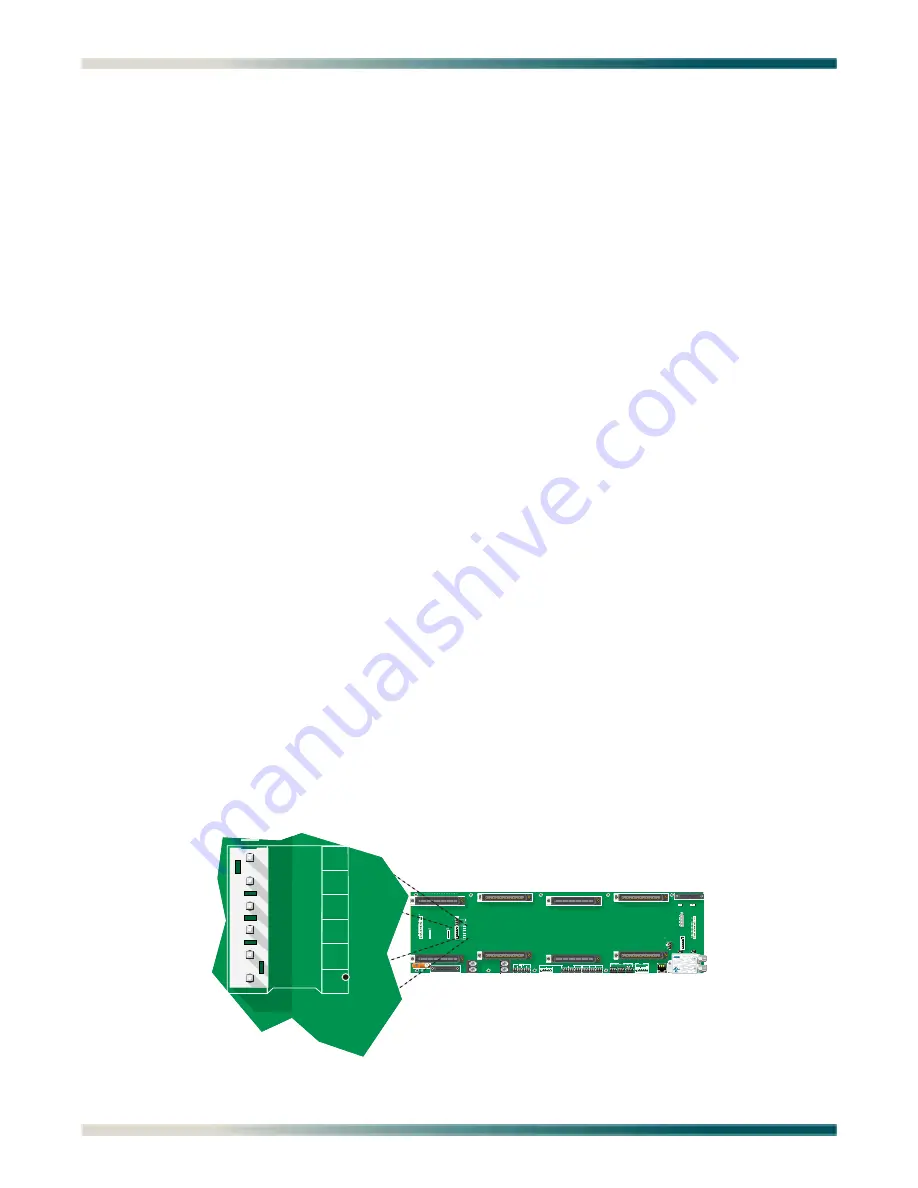
, P13, on the left side of the backplane. To wire the Total Access 3000 for MLT access,
perform the following steps:
1. After locating the test loops and running them to the Total Access 3000 chassis, use wire
strippers to strip approximately 1 to 1-1/2 inches from the test leads.
2. Using the wire-wrap tool, wire wrap the central office “T” and “R” leads to the Total Access
3000 “R” and “T” pins, respectively, on terminal P13.
3. Wire wrap the drain wire of the cable to the top pin labeled “S” on P13. If the drain wire
has been grounded at the test head, do not connect it to the “S” pin. Only one should be
grounded.
4. Wire wrap the central office “T1” and “R1” leads to the Total Access 3000 “R1” and “T1”
pins, respectively, on terminal P13.
5. Wire wrap the drain wire of the cable to the bottom pin labeled
S
on P13. If the drain wire
has been grounded at the test head, do not connect it to the
S
pin. Only one should be
grounded.
6. Neatly tie down the test cable pair.
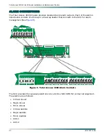
is an illustration of connecting MLT to the Total Access 3000 Chassis.
Figure 7. Total Access 3000 MLT Connections (T1 Only)
E D C B A
D C B A
F2
LOOP
TEST
ACCESS
33
1
64
32
33
1
64
32
33
1
64
32
33
1
64
64
32
ADMIN
J31
PAIR 2
P11
P12
P8
PAIR 3
PAIR 1
33
1
64
32
P10
PAIR 8
PAIR 6
PAIR 5
P9
P7
J33
EXTCLK
64
33
1
33
20
20
20
10
20
PAIR 7
1
10
20
32
1
64
32
33
1
NTWK MGMT
J30
-48 VDC PRI
-48 VDC
RET
P22
ACO
RMT
AUX1
AUX2
A
A
A
A
B
B
B
B
-48 VDC SEC
-48 VDC RET
P3
NO
NC
C
NO
NC
C
AUX1
AUX2
P21
CRI-A
NO C NC NO C NC NO C NC
MAJ-A
MIN-A
P1
P20
P2
J32
P19
P18
ALARM OUTPUTS
CRI-A
B - OUT
NO C NC NO C NC NO C NC
MAJ-A
MIN-A
A - OUT
B IN
E - NET
IN
OUT
+ –
+ – S
+ – S
+ – S
RS485
A B
A B
T
R
S
T1
R1
S
F1
10
30
20
40
48
E D C B A
P14
P15
S
S
30
40
48
1
6
T
R
T1
R1
P23
DSX1
TEST
ACCESS
F4
F3
PC2A 94V-0
2298
1
J1
S
1
R22
P24
EXTCLK
C-IN
1
10
20
8
+
–
R21
CUSTOM
TELECOM
E190349
1181004L1
PAIR 4
P5
Total Access
Chassis
LOOP
TEST
ACCESS
20
T
R
S
T1
R1
S
P13

