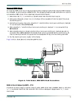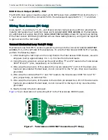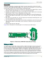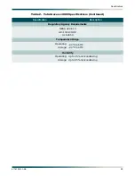
Network Management Connections
61181001L1-5E
25
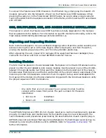
NOTE
In orde r for th e Hos t s helf to be use d in a da isy ch ain
configuration, the RS-485 bus must be enabled from the SCU
Provisioning menu (Provisioning > General > Management Ports >
Interbank Comm Mode > Host).
Replacing Rear Plastic Guard
If the Total Access 3000 Chassis has been installed step-by-step in the order presented, the
large Plexiglass guard may be replaced at this time. To replace the plastic guards, perform the
following steps:
1. Using a #1 phillips-head screwdriver, reattach the backplane guard to the backplane
using the four phillips head screws provided (two at each end).
2. Using a #1 phillips-head screwdriver, reattach the long thin guard to the backplane using
the two phillips head screws.
Connecting an External Modem
The Total Access 3000 Chassis can be accessed and managed via modem, allowing the same
capabilities to a user as if he were connected to the local craft access port on the front of the
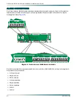
SCU. Access is provided by a DB-25 connector (J31), labeled
ADMIN
, located on the bottom
right corner of the backplane.
When the Total Access 3000 Chassis is “called,” the user can access not only the particular
chassis to which it is connected, but also any chassis daisy chained to it via the RS-485 bus.
To connect an external modem to the Total Access 3000, perform the following steps:
1. Mount the modem to be used with Total Access 3000 in its permanent position.
2. Connect power to the modem as per manufacturer’s instructions.
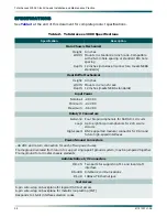
3. Configure the modem to be used as follows:
• Speed
9600 bps
• Data bits
8
• Parity
none
• Stop bits
1
• Flow control
off or none
• Auto Answer
on
• DTR
ignore
• RTS
ignore
• Config String
ATE0Q1S0 = 1&W0Y0
4. Connect the male DB-25 connector end of the data cable to the female DB-25 connector
(J31), labeled
ADMIN
, located on the lower right side of the Total Access 3000 backplane.
Use the screw provided with cable to fasten the DB-25 connection.
5. Route the data cable to the modem.

