Total Access 3000 23-Inch Chassis Installation and Maintenance Practice
26
61181001L1-5E
6. Connect the other end of the cable to the modem configured as described above.
7. Connect the modem to POTS line as required by the manufacturer.
NOTE
To complete the connection to the Total Access 3000 Chassis, the
Total Access 3000 must now be called from a PC configured as a
VT100 terminal with communication software.
Connecting the X.25
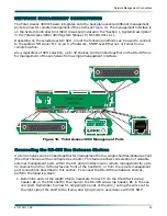
Total Access 3000 can send and receive TL1 commands for NMA management over the X.25
packet switched network. The Total Access 3000 Gateway SCU has a built-in X.25 PAD, and
the shelf is ready to connect to the network. Access to the network is via an RS-232 connector
(J30), labeled
NTWK MGMT
, located on the lower right side of the backplane. To connect the
X.25 to the Total Access 3000, perform the following steps:
1. Connect the DB-25 data cable male connector to the
NTWK MGMT
port, J30, on the Total
Access 3000 backplane.
2. Connect the other end of the data cable to the designated port of the X.25 switch.
NOTE
The CO X.25 network administrator must configure the X.25
switch for the Total Access 3000 Chassis, accomplishing tasks
such as assignment of an LDN number for the shelf.
NOTE
It is possible to remote the X.25 interface over a DDS line of up to
64 kbyte capacity, with the network designer designing the specific
interface. Some smaller COs without an X.25 switch may desire to
take advantage of this capability.
Connect 10Base-T
Total Access 3000 can provide SNMP management capability over Ethernet. The Total Access
3000 Gateway SCU has a built-in Ethernet interface, and the shelf is ready to connect to the
network. Access to the network is via an RJ-45 10Base-T connector (J32), labeled
E-NET
,
located on the lower right side of the backplane under the Pair 8 connector.
NOTE
ADTRAN recommends that the Total Access 3000 shelves not be
daisy-chained when using SNMP. For this configuration, each shelf
must be connected to an Ethernet hub.

