background image

Power Connections

61181001L1-5E

9

Power Connection

NOTE

Connect to a reliably grounded –48 VDC source that is electrically
isolated from the AC source.

NOTE

A readily accessible disconnect device, such as a rack mount fuse
and alarm panel that is suitably approved and rated, should be
incorporated in the fixed wiring. 

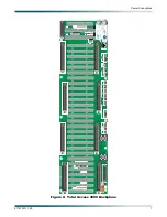
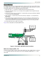
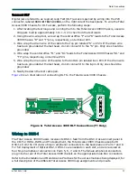
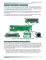
Dual power buses are provided with separate battery returns. Power connections use two 
separate opposing blocks, labeled 

TS1

 and 

TS2

, located on the lower left side of the backplane 

below the Pair 5 amphenol connector (see 

Figure 3

). The terminals are on 0.4375 inch centers 

and allow for wire gauges up to 10 AWG. There is a separate Frame Ground terminal, labeled 

FR GND

, located on the bottom left side of the backplane, and can accommodate up to 8 AWG 

wire. The two power inputs, 

TS1

 and 

TS2

, are identical in function and can be used for 

redundant power configurations. The Frame Ground terminal routes to mechanical contact 
points and provides an electrical connection to the chassis metalwork. The two power buses 
and Frame Ground route to all the cards in the chassis. Plug-in cards are responsible for any 
necessary DC-DC conversion.

Figure 4

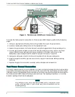
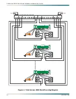
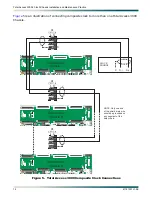
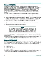
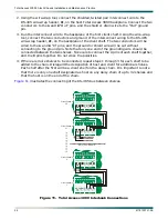
 depicts how the Total Access 3000 Chassis can be powered from a typical dual-feed 

fuse and alarm panel. Seven shelves are depicted. The number of shelves that can be placed in 
a 7-foot central office rack depends on the type of service deployed, the number of access 
modules in the chassis, and, in the case of HDSL or T1, the number of repeaters being 
powered.
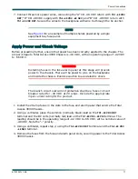
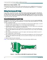
After connecting and checking the ground to the Total Access 3000 Chassis, connect power to 
the chassis. Check to make sure the power source is providing the correct power and polarity 
to the chassis. To connect power to the chassis, perform the following steps:

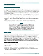
1. Determine which fuse pairs are to supply power to the Total Access 3000 chassis.
2. Remove the fuses from the 

A

 and 

B

 slots for the pair determined in the above.

3. Using a #1 phillips-head screwdriver, remove the Plexiglass cover to the power terminals,  

labeled 

TS1

 and 

TS2

.

4. Cut four lengths of AWG 10 wire to reach from the terminals on the fuse and alarm panel 

to the power terminals on the Total Access 3000 Chassis. Be sure to include enough 
length to allow for tying the wire neatly to the frame as specified by CO SOP.

5. Using the crimping tool, connect an appropriate lug to each end of the wires.
6. Using a screwdriver appropriate for the fuse and alarm panel terminals, and a straight 

slot screwdriver for the Total Access 3000 Chassis power terminal, connect the ends of 
one wire between the “A” CO –48 VDC supply and the 

–48 VDC –48 PRI

 terminal on the Total 

Access 3000 backplane. Secure the wire to the backplane with wire tie through the tie 
anchor.

Summary of Contents for 1181001L1

Page 1: ...Total Access 3000 23 Inch Chassis Installation and Maintenance Practice Document Number 61181001L1 5E CLEI M3M1BB0B_ _ November 2005...

Page 2: ...of the Manual The contents of this publication are current as of the date of publication ADTRAN reserves the right to change the contents without prior notice In no event will ADTRAN be liable for an...

Page 3: ...ls or other system label items This font is used for strong emphasis NOTE Notes inform the user of additional but essential information or features CAUTION Cautions inform the user of potential damage...

Page 4: ...iews on product features and functions while covering applications of ADTRAN product lines ADTRAN provides a variety of training options including customized training and courses taught at our facilit...

Page 5: ...age 11 Data Connections 12 Removing Rear Plastic Guards 12 Wiring Clocks 12 Connect 64 kHz Composite Clock 12 Connect BITS Clock 15 MUX A Clock Output A OUT P19 15 MUX B Clock Output B OUT P20 16 Wiri...

Page 6: ...hnical Support A 1 ADTRAN Repair CAPS A 1 Repair and Return Address A 1 Figures Figure 1 Total Access 3000 23 Inch Chassis 1 Figure 2 Total Access 3000 Backplane 7 Figure 3 Total Access 3000 Power Con...

Page 7: ...3000 23 Inch Chassis The Total Access 3000 system can function as either a DSLAM or as a TDM platform When used as a DSLAM the Total Access 3000 can be used to provide services such as xDSL SHDSL DSX...

Page 8: ...n and in a Type B or E enclosure only CAUTION Per GR 1089 CORE October 2002 Section 9 the Total Access 3000 Chassis is designed and intended only for installation in a DC C common bonding and groundin...

Page 9: ...ls Required The required tools for the Total Access 3000 installation are as follows Wire wrap tool 2 phillips head screwdriver 1 phillips head screwdriver Straight slot head screwdriver Multimeter Cr...

Page 10: ...ng storm CAUTION Electronic modules can be damaged by static electrical discharge Before handling modules wear an antistatic discharge wrist strap to prevent damage to electronic components Place modu...

Page 11: ...Mid mounting For mid mounting use a 2 phillips head screwdriver and attach the mounting brackets to the Total Access 3000 Chassis with the flanges facing forward on the front mounting holes Installin...

Page 12: ...on the backplane Figure 2 illustrates the backplane and Figure 3 indicates the location of the power and ground connec tions Frame Ground Connection The frame ground lug located on the lower left cor...

Page 13: ...A P A I R 7 1 10 20 32 1 J17 10 20 32 1 10 20 32 1 J15 10 20 32 1 J14 10 20 32 1 J13 10 32 1 J12 20 20 32 1 J11 10 32 1 J10 10 20 20 32 1 J9 10 20 32 1 J8 10 20 32 1 J7 20 32 1 J6 10 10 20 32 C B A C...

Page 14: ...d be investigated NOTE The Ethernet port Dual and Quad BNC ports composite clock ports and any DSX 1 port must only be connected to intra building wiring TOTAL ACCESS CHASSIS E D C B A D C B A F2 LOOP...

Page 15: ...ven shelves are depicted The number of shelves that can be placed in a 7 foot central office rack depends on the type of service deployed the number of access modules in the chassis and in the case of...

Page 16: ...33 20 20 20 10 20 PAIR 7 1 10 20 32 1 64 32 33 1 NTWK MGMT J30 48 VDC PRI 48 VDC RET P22 ACO RMT AUX1 AUX2 A A A A B B B B 48 VDC SEC 48 VDC RET P3 NO NC C NO NC C AUX1 AUX2 P21 CRI A NO C NC NO C NC...

Page 17: ...the chassis There will be power to pins on the backplane and inside the chassis Exercise caution to avoid electric shock NOTE The branch circuit overcurrent protection shall be a fuse or circuit break...

Page 18: ...er to thread the wire ties through the anchors while the backplane guard is removed ADTRAN recommends using the wire ties provided to secure the amphenol connectors Thread the wire ties through the an...

Page 19: ...o a single external timing source perform the following steps 1 Determine the length of wire required to run from the first chassis connector P4 to the second chassis connector P4 that is to be wired...

Page 20: ...GMT J30 48 VDC PRI 48 VDC RET P22 ACO RMT AUX1 AUX2 A A A A B B B B 48 VDC SEC 48 VDC RET P3 NO NC C NO NC C AUX1 AUX2 P21 CRI A NO C NC NO C NC NO C NC MAJ A MIN A P1 P20 P2 J32 P19 P18 ALARM OUTPUTS...

Page 21: ...is an illustration of connecting BITS clock Figure 6 Total Access 3000 BITS Clock Connections MUX A Clock Output A OUT P19 The MUX A clock output is used to output a DS1 BITS clock from a SONET MUX A...

Page 22: ...Wire wrap the drain wire of the cable to the top pin labeled S on P13 If the drain wire has been grounded at the test head do not connect it to the S pin Only one should be grounded 4 Wire wrap the ce...

Page 23: ...sis receives its DSX 1 feed from the DSX cross connect panel in the CO For HDSL ISDN and T1 deployment the Total Access 3000 Chassis accepts 28 DSX 1s from the CO via two 64 pin amphenol connectors to...

Page 24: ...a side cutter snip the wire tie end off flush with the barrel of the tie 4 Repeat steps 1 4 for each connector on the backplane being used for the intended application 5 Neatly tie off the data cables...

Page 25: ...the 24 pin female connector on the backplane Lining up these pins and holes will align the screw holes in the adapter module with the threaded press fittings in the backplane NOTE The 24 pins on the...

Page 26: ...TCLK 64 33 1 33 20 20 20 10 20 PAIR 7 1 10 20 32 1 64 32 33 1 NTWK MGMT J30 48 VDC PRI 48 VDC RET P22 ACO RMT AUX1 AUX2 A A A A B B B B 48 VDC SEC 48 VDC RET P3 NO NC C NO NC C AUX1 AUX2 P21 CRI A NO...

Page 27: ...rand to the center pin common from the Total Access alarm relay header and the other strand to either the NO normally open or NC normally closed pin on the relay header 5 Connect using wire wrap or lu...

Page 28: ...e alarm pair when an alarm condition exists 3 Using wire strippers strip 1 to 2 inches from both ends of the wire 4 Using a wire wrap gun wire wrap one wire to the B pin of the Total Access 3000 AUX1...

Page 29: ...terface on front of the host SCU or from the remote management port connections described in this section To connect the RS 485 bus between shelves perform the following steps 1 Determine and cut the...

Page 30: ...pin Note that only one end of the grounding wire should be connected between the two shelves Take care to connect the A pins of each shelf together and the B pins together Do not cross the polarities...

Page 31: ...es to a user as if he were connected to the local craft access port on the front of the SCU Access is provided by a DB 25 connector J31 labeled ADMIN located on the bottom right corner of the backplan...

Page 32: ...r to the NTWK MGMT port J30 on the Total Access 3000 backplane 2 Connect the other end of the data cable to the designated port of the X 25 switch NOTE The CO X 25 network administrator must configure...

Page 33: ...arrier and then contact ADTRAN Customer Service Installing Modules The SCU must be placed in the slot labeled SCU Multiplexer or Cell Switch Modules must be placed in either the slot labeled A or B Ac...

Page 34: ...imum 48 VDC 42 VDC 56 VDC Data I O Connectors Network Loop High speed Four 64 pin amphenols for 56 DSX 1 circuits Up to eight 64 pin amphenols for 224 2 wire circuits BNC supported modular connector f...

Page 35: ...rements NEBS LEVEL 3 GR 1089 CORE UL 60950 Temperature Range Operating Storage 40 C to 65 C 40 C to 85 C Humidity Operating Storage Up to 95 noncondensing Up to 95 noncondensing Table 2 Total Access 3...

Page 36: ...Total Access 3000 23 Inch Chassis Installation and Maintenance Practice 30 61181001L1 5E This page is intentionally blank...

Page 37: ...s support Customer and Product Service CAPS requests or further information ADTRAN Sales Pricing Availability 800 827 0807 ADTRAN Technical Support Pre Sales Applications Post Sales Technical Assistan...

Page 38: ...Carrier Networks Division 901 Explorer Blvd Huntsville AL 35806...

Reviews: