


Data Connections
61181001L1-5E
13
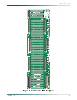
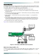
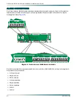
3. Using the wire-wrap tool, wire wrap the “
+
” wire from the clock source to the pin marked
“
+
” on connector P10,
EXTCLK A-IN
.
4. Wire wrap the “
–
” wire from the clock source to the pin marked “
–
” on connector P4,
EXTCLK A-IN
.
5. Wire wrap the drain or shield wire from the clock source to the pin marked
S
on connector
P4,
EXTCLK A-IN
.
NOTE
If the drain or shield is connected to the clock source, then the
drain or shield does not need to be connected to the
S
pin of P4.
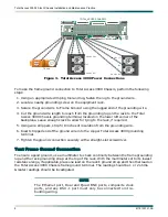
6. Tie the clock source wire neatly to the frame.
7. On the daughterboard mounted to the left of, and slightly below, P4, move the jumper so
that the left two pins labeled
TERM IN
, are connected together.
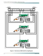
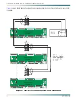
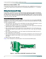
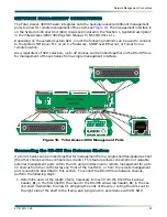
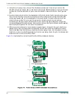
Up to eight Total Access 3000 Chassis may be daisy chained to a single output from the
timing source, so only one wire run is required from the timing source for an installation of up
to eight Total Access 3000 Chassis. Use wire of the same type as was used for the wire run
from the CO clock source to the Total Access 3000 Chassis. To connect up to eight Total
Access 3000 Chassis to a single external timing source, perform the following steps:
1. Determine the length of wire required to run from the first chassis, connector P4, to the
second chassis, connector P4, that is to be wired in the same daisy chain. Leave approxi-
mately 1 to 1-1/2 inches for wire wrapping.
2. Using wire strippers, strip approximately 1 to 1 -1/2 inches from both ends of the wire
run.
3. Using a wire wrap tool, wire wrap the “
+
”, “
–
” and drain wires to the “
+
”, “
–
” and “
S
”
terminal pins of connector P4,
A-IN
, on the backplane.
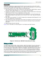
4. Run the wire from P10 on the “source” shelf to connector P4,
EXTCLK A-IN
, on the receiving
shelf.
5. Wire wrap the “
+
”, “
–
” of the wire run to the “
+
”, “
–
” terminals of P4 on the receiving shelf.
6. On the daughterboard of the receiving shelf, mounted to the left of, and slightly below P4,
move the jumper so that the right two pins, labeled
TERM OUT
, are connected together.
7. Repeat steps 1-6 for each Total Access 3000 Chassis, up to a total of eight in the daisy
chain, that is to be interconnected on the single CO timing source.
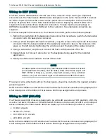
NOTE
In any daisy chain of Total Access 3000 Chassis using a single
timing source, only the first shelf in the chain should have the
timing daughterboard jumpered to
TERM IN
. All the remaining
chassis in the chain should have the daughterboard jumpered to
TERM OUT
.


