Chapter 2. Installation
2-2
Dual U-BR1TE Plug-in Option Card User Manual
61200107L1#HS-1
Provided by Customer
The customer must provide cables for connection to othe
equipment.
DUAL U-BR1TE PLUG-IN OPTION CARD INSTALLATION
Placement of the Option Module
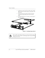
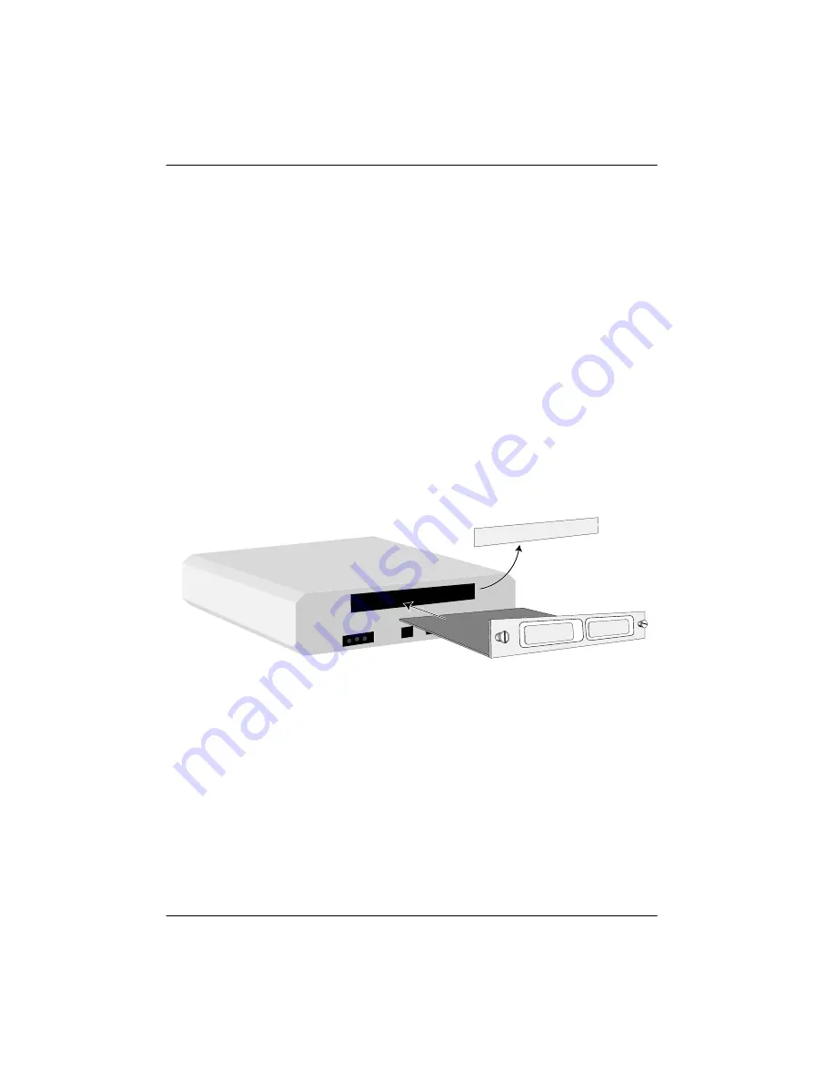
Figure 2-1 represents the action required for proper place-
ment of the option module.
1.
Remove cover plate from the rear panel.
2.
Slide option module into the rear panel until it is
positioned firmly against the front of the unit.
3.
Fasten thumb-screws at both edges of option mod-
ule.
Figure 2-1. Installing the Option Module
Power Connection
Each option module derives power from the base TSU/
120/600 unit. Power to the base unit is supplied by a cap-
tive eight foot power cord.
Cover Plate
Option Module
TSU 100/120/600
Summary of Contents for 1200107L1
Page 12: ...List of Figures xii Dual U BR1TE Plug in Option Card User Manual 61200107L1 HS 1 ...
Page 14: ...List of Tables xiv Dual U BR1TE Plug in Option Card User Manual 61200107L1 HS 1 ...
Page 24: ...Chapter 2 Installation 2 6 Dual U BR1TE Plug in Option Card User Manual 61200107L1 HS 1 ...
Page 40: ...iv ...


