background image

Chapter 3. Operation

3-4

Dual U-BR1TE Plug-in Option Card User Manual

61200107L1#HS-1

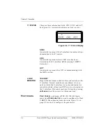
T1 STATUS

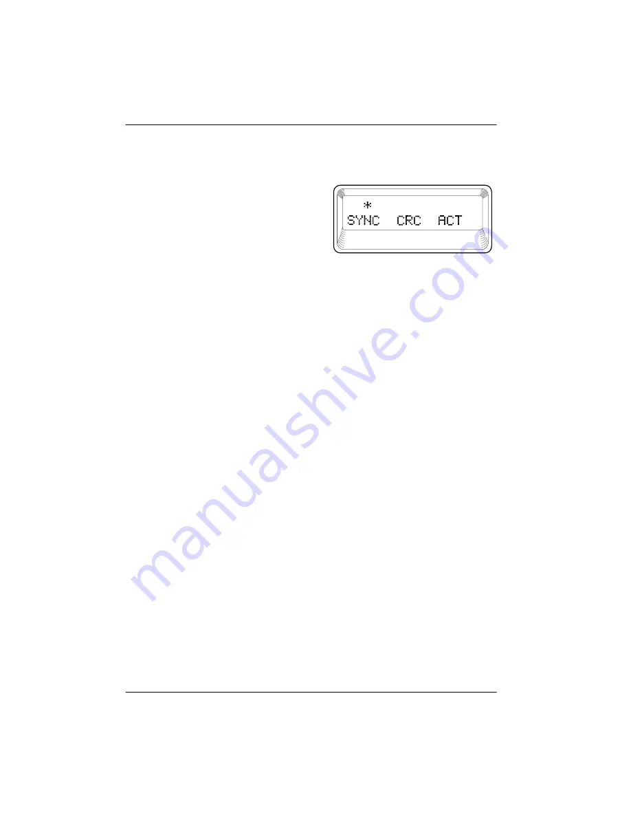
There are three information fields: SYNC, CRC, and ACT.
See Figure 3-4. An asterisk indicates an item is active.

Figure 3-4. T1 S

TATUS

Display

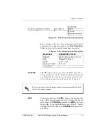
SYNC

An asterisk is present if the U-interface has achieved syn-
chronization to the T1 carrier.

CRC

An asterisk is present when a CRC error has been
detected on the T1 interface. (DS0s carrying U-BR1TE
data only.)

ACT

An asterisk is present if an NT1 is communicating with
the ISDN switch.

LOOP
MONITOR

"ES=XXX"

Reports the maximum number of errored seconds on the
U-interface. Errored seconds are considered to be sec-
onds in which the U-interface was not synchronized or
seconds in which at least one CRC error was detected on
the U-interface. This count can be set to zero by pressing

shift-clear

when the cursor is at this menu item.

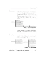
P

ORT

C

ONFIG

P

ORT

C

ONFIG

, a submenu of TSU 100/120/600 main

menu item

C

ONFIGURATION

, is used to configure the Dual

U-BR1TE. The submenu items shown in Figure 3-5 on
page 3-5 are used to configure the parameters.

Summary of Contents for 1200107L1

Page 1: ...Dual U BR1TE Plug In Option Card Part Number 1200107L1 HS and Dual U BR1TE Plug On Option Card Part Number 1200108L1 USER MANUAL 61200107L1 HS 1B June 2000 ...

Page 2: ...901 Explorer Boulevard P O Box 140000 Huntsville AL 35814 4000 256 963 8000 2000 ADTRAN Inc All Rights Reserved Printed in U S A ...

Page 3: ... provide additional useful information Cautions signify information that could prevent service interrup tion Warnings provide information that could prevent damage to the equipment or endangerment to human life ...

Page 4: ...on of this equipment advance notification and the opportunity to maintain uninterrupted service is given 4 If experiencing difficulty with this equipment please contact ADTRAN for repair and warranty information The telephone company may require this equipment to be disconnected from the network until the problem is cor rected or it is certain the equipment is not malfunctioning 5 This unit contai...

Page 5: ...which case the user will be required to correct the inter ference at his own expense Shielded cables must be used with this unit to ensure compliance with Class A FCC limits CANADIAN EMISSIONS REQUIREMENTS This digital apparatus does not exceed the Class A limits for radio noise emis sions from digital apparatus as set out in the interference causing equipment standard entitled Digital Apparatus I...

Page 6: ...ns Repairs to certified equipment should be made by an authorized Canadian main tenance facility designated by the supplier Any repairs or alterations made by the user to this equipment or equipment malfunctions may give the telecommu nications company cause to request the user to disconnect the equipment Users should ensure for their own protection that the electrical ground connec tions of the p...

Page 7: ...ty of the leak 4 Use only the power cord power supply and or batteries indicated in the manual Do not dispose of batteries in a fire They may explode Check with local codes for special disposal instructions WARRANTY AND CUSTOMER SERVICE ADTRAN will replace or repair this product within five years from the date of shipment if it does not meet its published specifications or fails while in service F...

Page 8: ...ty becomes null and void if Customer modifies or alters the equipment in any way other than as specifically authorized by ADTRAN EXCEPT FOR THE LIMITEDWARRANTY DESCRIBED ABOVE THE FOREGO ING CONSTITUTES THE SOLE AND EXCLUSIVE REMEDY OF THE CUS TOMER AND THE EXCLUSIVE LIABILITY OF ADTRAN AND IS IN LIEU OF ANY AND ALL OTHER WARRANTIES EXPRESSED OR IMPLIED ADTRAN SPECIFICALLY DISCLAIMS ALL OTHER WARR...

Page 9: ...wer Up 2 1 Receipt Inspection 2 1 ADTRAN Shipments Include 2 1 Provided by Customer 2 2 Dual U BR1TE Plug In Option Card Installation 2 2 Placement of the Option Module 2 2 Power Connection 2 2 Wiring 2 3 Attaching the Plug on Board to the Option Card 2 3 Power Up Testing and Initialization 2 5 Successful Self Test 2 5 Failed Self Test 2 5 Operation Alarms 2 5 Chapter 3 Operation 3 1 Overview 3 1 ...

Page 10: ...Table of Contents x Dual U BR1TE Plug in Option Card User Manual 61200107L1 HS 1 Appendix A Dual U BR1TE Option Card Menu Tree A 1 Appendix B Dual U BR1TE Failure Messages B 1 ...

Page 11: ...g the Option Module 2 2 Figure 2 2 Installing Plug on Board 2 4 Figure 3 1 TSU 100 Main Menu 3 2 Figure 3 2 PORT STATUS Submenus 3 3 Figure 3 3 LOOP STATUS Display 3 3 Figure 3 4 T1 STATUS Display 3 4 Figure 3 5 PORT CONFIGURATION Submenus 3 5 Figure 3 6 Network Locations 3 6 Figure 3 7 PORT UTILITY Submenus 3 7 Figure 3 8 PORT TEST Submenus 3 7 Figure A 1 Dual U BR1TE Option Cards Menu Tree A 1 ...

Page 12: ...List of Figures xii Dual U BR1TE Plug in Option Card User Manual 61200107L1 HS 1 ...

Page 13: ...1200107L1 HS 1 Dual U BR1TE Plug in Option Card User Manual xiii List of Tables Table 2 1 2 Wire Voice Pinout Connection 2 3 Table 3 1 PORT CONFIGURATION Parameters 3 5 Table 3 2 PORT TEST Parameters 3 8 ...

Page 14: ...List of Tables xiv Dual U BR1TE Plug in Option Card User Manual 61200107L1 HS 1 ...

Page 15: ...the host T1 multiplexer s operation and control The Dual U BR1TEs provide two ISDN U interfaces and allow the transport of Basic Rate ISDN BRI information over T1 carriers and unloaded twisted pair wiring Functional Description The Dual U BR1TEs are configured in the same manner as the host multiplexer The internal menu for the configu ration of each U BR1TE is a part of the Dual U BR1TE Module an...

Page 16: ...able to line unit LT or line unit NT mode of operation Loopback capability for full 2B D as well as individ ual B channels in both loop and carrier directions B1 and B2 looopback addressability for the NT1 and up to six devices in the downstream toward the NT1 direction Local performance monitoring without test equip ment Dual U BR1TE Option Card The Dual U BR1TE Option Cards conform to the follow...

Page 17: ... X Y indication is linked to the port numbering philosophy of the TSU 100 product fam ily The X represents the slot number and the Y indicates the port number For the TSU 100 application there is only one option slot Therefore the ports are designated 1 1 and 1 2 If added the plug on board port designations ISDN 2B1Q Inter face ANSI T1 601 1992 Performance TR NWT 000397 and TR TSY 000829 ISDN BR o...

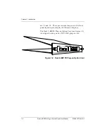
Page 18: ...4 These port numbers appear in the front panel liquid crystal display LCD menu displays The Dual U BR1TE Plug on Option Card see Figure 1 2 is designed to plug on any TSU DSU plug in card Figure 1 2 Dual U BR1TE Plug on Option Card PORT X 1 DUAL U BR1TE DUAL U BR1TE PORT X 3 X 4 HOT REPLACEABLE PORT X 2 ...

Page 19: ...ble keep the original shipping container for use in shipping the option module for repair or for verification of damage during shipment ADTRAN Shipments Include The following items are included in ADTRAN shipments of the Dual U BR1TE Dual U BR1TE Plug in Option Card Dual U BR1TE Plug in Option Card User Manual to be inserted into main TSU 100 120 600 User Manual Dual U BR1TE Plug on Option Card Du...

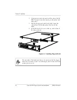
Page 20: ...n required for proper place ment of the option module 1 Remove cover plate from the rear panel 2 Slide option module into the rear panel until it is positioned firmly against the front of the unit 3 Fasten thumb screws at both edges of option mod ule Figure 2 1 Installing the Option Module Power Connection Each option module derives power from the base TSU 120 600 unit Power to the base unit is su...

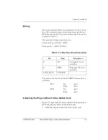
Page 21: ... Connector Type USOC RJ 45 Part number AMP 555164 1 Table 2 1 2 Wire Voice Pinout Connection Pins used to mate with the Dual U BR1TE connector are as follows Attaching the Plug on Board to the Option Card Figure 2 2 represents the action required for proper place ment of a plug on board on the option card 1 Hold the plug on board above the option card Pin Name Description 5 TIP Tip lead of 2 wire ...

Page 22: ...he plug on board downward secure the connection of the header pins at the front of the board 4 Install the four 4 40 screws at the top and bottom of the plug on board Figure 2 2 Installing Plug on Board Nx 54 64 V 35 Nx 56 64 Port X 1 V 35 DXC The connection of the header pins between the option card and the plug on board must be visually verified Severe damage of the device can result from an imp...

Page 23: ...tically upon power up Successful Self Test The green OK LED located on the front panel turns on when a successful self test is completed and the configu ration is successfully restored See the chapter Operation in the main user manual Failed Self Test If the Dual U BR1TE card fails one or more of the self tests a message is displayed in the LCD during power up See the TSU 100 120 600 user manual S...

Page 24: ...Chapter 2 Installation 2 6 Dual U BR1TE Plug in Option Card User Manual 61200107L1 HS 1 ...

Page 25: ...ons under the Port menu items These menu items are shaded in the limited overview of the TSU 100 menu shown in Figure 3 1 on page 3 2 The appendix of the TSU 100 User Manual shows a complete menu diagram Menu Operation An option module must be selected from the listing in one of the Port menu options before any option module menus are applicable With the cursor on one of the Port menu items press ...

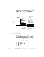
Page 26: ... 600 The Dual U BR1TE items are submenu choices of those four main menus as shown in Figure 3 1 For information on FAC TORY RESTORE and RUN SELF TEST see TSU Features used with Dual U BR1TE Options on page 3 9 The Dual U BR1TE menu items are as follows PORT STATUS PORT CONFIGURATION PORT UTILITY PORT TEST TSU 100 MAIN MENU 1 STATUS 2 CONFIG 3 UTIL 1 NI PERF REPORTS 2 NI ERRORS 3 ACTIVE ALARMS 4 VI...

Page 27: ...ubmenus shown in Figure 3 2 Figure 3 2 PORT STATUS Submenus LOOP STATUS There are three information fields SYNC CRC and ACT See Figure 3 3 An asterisk indicates an item is active Figure 3 3 LOOP STATUS Display SYNC An asterisk is present if the U interface has achieved syn chronization CRC An asterisk is present when a CRC error has been detected on the U interface ACT An asterisk is present if an...

Page 28: ...ata only ACT An asterisk is present if an NT1 is communicating with the ISDN switch LOOP MONITOR ES XXX Reports the maximum number of errored seconds on the U interface Errored seconds are considered to be sec onds in which the U interface was not synchronized or seconds in which at least one CRC error was detected on the U interface This count can be set to zero by pressing shift clear when the c...

Page 29: ... to transmit and receive data All switched applications will require the D channel ZBS For proper operation the ZBS zero byte substitution for two U BR1TE ports connected by a T1 facility must be the same value The ENABLE parameter for ZBS must be se lected if the T1 is using AMI line coding If the T1 facility is using B8ZS line coding the DISABLE parameter may be chosen 1 SERVICE 2 CONFIG 7 PORT ...

Page 30: ...ation or when it is adjacent to a device that requires wake up tones Figure 3 6 Network Locations ISDN Switch Dual U BR1TE Port TSU Dual U BR1TE Port TSU Customer NT1 Dual U BR1TE Port TSU Customer NT1 Customer NT1 Dual U BR1TE Port TSU 2 Wire T Carrier 2 Wire Loop 2 Wire 2 Wire T Carrier T Carrier 2 Wire Loop 2 Wire Loop Adjacent to Switch Adjacent to Customer Adjacent to Switch Tandem Office Sou...

Page 31: ...s Display 1 1 UBR1TE scroll to display if necessary and press Enter The unit displays the option card name and the software version installed Press Cancel to exit or se lect another port PORT TEST PORT TEST a submenu of the TSU 100 120 600 main menu item TEST activates tests of the selected data ports Selecting the Dual U BR1TE displays tests available for this option card See Figure 3 8 Figure 3 ...

Page 32: ...e test The user can view the pattern results by choosing menu item 7 PATT RESULTS and can inject errors into the transmitted pattern by choosing menu item 6 INJECT ERROR Select NO LOOPBACK under the B1 REMOTE LPBK menu to exit the test B2 REMOTE LPBK The B2 REMOTE LPBK operates exactly like the B1 RE MOTE LPBK TEST but the B2 channel is looped back rath er than the B1 channel LOCAL LPBK The local ...

Page 33: ...cting this menu item while the U BR1TE is transmit ting the 2047 pattern B1 REMOTE LPBK B2 REMOTE LPBK B1 2047 PATT B2 2047 PATT inserts an error in the transmitted pattern PATT RESULTS Selecting this menu item while the U BR1TE is transmit ting the 2047 pattern causes the U BR1TE to display the maximum number of errored seconds of the test pattern on the bottom line of the LCD ES xs The display c...

Page 34: ...configuration parameters is shown in Table 3 1 on page 3 5 RUN SELF TEST RUN SELF TEST a submenu of the TSU 100 120 600 main menu item TEST executes both the Dual U BR1TE inter nal test and the TSU 100 120 600 internal test The results of the self test are displayed in the LCD See the TSU 100 120 600 User Manual for additional information on SELF TEST When RUN SELF TEST is displayed place the curs...

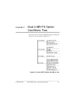
Page 35: ...and Plug on Option Cards is provided in Figure A 1 Figure A 1 Dual U BR1TE Option Cards Menu Tree 1 Port Status 1 LOOP STATUS 2 T1 STATUS 3 LOOP MONITOR 1 SERVICE 2 Port Config 2 ZBS 3 MODE 4 WAKE UP TONE 3 Port Utility 1 SW Revision 1 B1 REMOTE LPBK 2 B2 REMOTE LPBK 4 Port Test 3 LOCAL LOOPBACK 4 B1 2047 PATT 5 B2 2047 PATT 6 INJECT ERROR 7 PATT RESULTS ...

Page 36: ...Appendix A Dual U BR1TE Option Card Menu Tree A 2 Dual U BR1TE Plug in Option Card User Manual 61200107L1 HS 1 ...

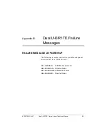
Page 37: ...x B Dual U BR1TE Failure Messages FAILURE MESSAGE AT POWER UP The following messages indicate a probable component failure on the Dual U BR1TE Card E01 EPROM CS EPROM checksum error E02 RAM DATA Data Bus Failure E03 RAM ADDR Address Bus Failure E04 RAM CELL Ram Cell Failure ...

Page 38: ...Appendix B Dual U BR1TE Failure Messages B 2 Dual U BR1TE Plug in Option Card User Manual 61200107L1 HS 1 ...

Page 39: ...repair is needed Technical Sup port will coordinate with the Customer and Product Service CaPS department to issue an RMA number For information regarding equipment currently in house or possible fees associated with repair contact CaPS directly at the following num ber Identify the RMA number clearly on the package below address and return to the following address ADTRAN Inc CaPS Department 6767 ...

Page 40: ...iv ...
Reviews: