Chapter 1. Introduction
61200315L1-1
Quad BRI/U Module User Manual
1-3
PHYSICAL DESCRIPTION
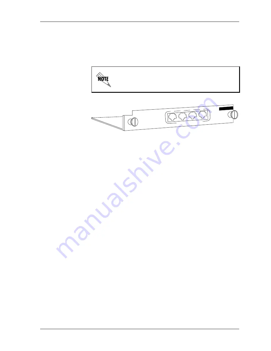
The Quad BRI/U Module (see Figure 1-2) plugs into any available option
slot in the rear of the ATLAS chassis.
Figure 1-2. Quad BRI/U Module
The label over each RJ-45 connector refers to the port on the Quad BRI/U
Module.
The four Option slots (labeled 1 — 4) only accept Option Modules,
and the Network Interface slots (labeled Network 1 and Network 2)
only accept Network Interface Modules. (See the ATLAS 550 in
Figure 2-1 on page 2-2.)
1
2
3
4
ISDN BRI U INTERF
ACE
500 Series
Summary of Contents for 1200315L1
Page 1: ...Quad BRI U Module User Manual Part Number 1200315L1 61200315L1 1B April 2000 ...
Page 8: ...viii ...
Page 12: ...List of Figures xii Quad BRI U Module User Manual 61200315L1 1 ...
Page 14: ...List of Tables xiv Quad BRI U Module User Manual 61200315L1 1 ...
Page 18: ...Chapter 1 Introduction 1 4 Quad BRI U Module User Manual 61200315L1 1 ...
Page 22: ...Chapter 2 Installation 2 4 Quad BRI U Module User Manual 61200315L1 1 ...
Page 34: ...Appendix A Dial Plan Configuration A 6 Quad BRI U Module User Manual 61200315L1 1 ...
Page 36: ...Index Index 2 Quad BRI U Module User Manual 61200315L1 1 ...
Page 38: ......


