background image

61200315L1-1

Quad BRI/U Module User Manual

A-1

Appendix A

Dial Plan Configuration

DIAL PLAN OVERVIEW

The

D

IAL

P

LAN

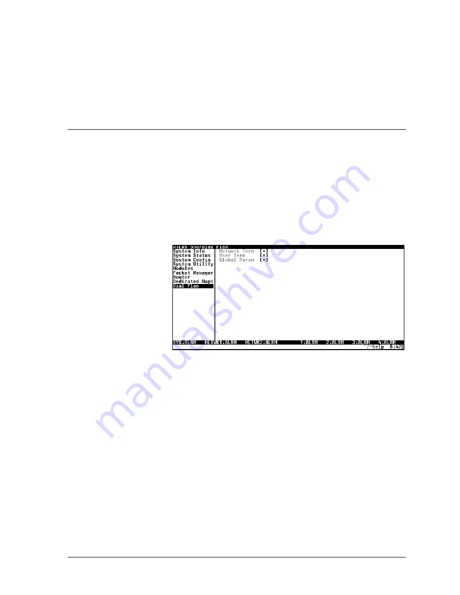
menu (see Figure A-1) sets configuration parameters for each

switched endpoint. These parameters vary by the type of port selected. The
following sections describe the configuration options available for the Quad
BRI/U Module. The

D

IAL

P

LAN

menus are only accessible when using a VT-

100 or Telnet session. To access these options, select

D

IAL

P

LAN

from the top

level menu.

Figure A-1. Dial Plan Menus

QUAD BRI/U MODULE CONFIGURATION

This section describes the

N

ETWORK

T

ERMINATION

and

U

SER

T

ERMINATION

configuration settings for the Quad BRI/U Module when using the

D

IAL

P

LAN

menus.

See Quad BRI/U Module: Network Termination on page A-2.

See Quad BRI/U Module: User Termination on page A-3.

Summary of Contents for 1200315L1

Page 1: ...Quad BRI U Module User Manual Part Number 1200315L1 61200315L1 1B April 2000 ...

Page 2: ...901 Explorer Boulevard P O Box 140000 Huntsville AL 35814 4000 256 963 8000 2000 ADTRAN Inc All Rights Reserved Printed in U S A ...

Page 3: ...n the network The affidavit shall affirm that either no encoded analog content or billing information is being transmitted or that the output of the device meets Part 68 encoded analog content or billing protec tion specifications End user customer will be responsible for filing an affidavit with the local exchange carrier when connecting unprotected customer premise equipment CPE to 1 544 Mbps or...

Page 4: ...t under the control of the customer I attest that the operator s maintainer s of the digital CPE responsible for the establishment mainte nance and adjustment of the encoded analog content and billing information has have been trained to perform these functions by successfully having completed one of the following check appropriate blocks A A training course provided by the manufacturer grantee of...

Page 5: ... warranty information The telephone company may ask you to discon nect this equipment from the network until the problem has been corrected or until you are sure the equipment is not malfunctioning 6 This unit contains no user serviceable parts 7 The following information may be required when applying to your local telephone company for leased line facilities Federal Communications Commission FCC ...

Page 6: ...sed by the device to prevent overloading The termination on a loop may consist of any combination of devices subject only to the equipment that the total of the LNs of all devices does not exceed 100 The ringer equivalence number REN assigned to each terminal adapter is used to determine the total number of devices that may be connected to each circuit The sum of the RENs from all devices in the c...

Page 7: ...rranty becomes null and void if Customer modifies or alters the equipment in any way other than as specifically authorized by ADTRAN EXCEPT FOR THE LIMITEDWARRANTY DESCRIBED ABOVE THE FOREGOING CONSTITUTES THE SOLE AND EXCLUSIVE REMEDY OF THE CUSTOMER AND THE EXCLUSIVE LIABILITY OF ADTRAN AND IS IN LIEU OF ANY AND ALL OTHER WARRANTIES EXPRESSED OR IMPLIED ADTRAN SPECIFICALLY DISCLAIMS ALL OTHER WA...

Page 8: ...viii ...

Page 9: ... Installing the Quad BRI U Module 2 1 Shipping Contents 2 1 Installing the Quad BRI U Module 2 1 Wiring 2 3 Power Up and Initialization 2 3 Failed Self Test 2 3 Operation Alarms 2 3 Chapter 3 Operation 3 1 Overview 3 1 Terminal Menu Structure 3 1 Modules Menu 3 2 Slt 3 2 Type 3 3 Menu 3 3 Alarm 3 3 Test 3 3 State 3 3 Status 3 3 Online 3 3 No Response 3 4 Empty 3 4 Offline 3 4 Offline No Response 3...

Page 10: ...m 3 5 Prt 3 5 Alarms 3 5 Channel Status 3 5 Prt 3 5 Cha 3 5 Performance Current 3 5 Configuration 3 5 Test 3 5 Module Alarms 3 5 Test Activity 3 5 ATLAS Features Used with Quad BRI U Module Options 3 6 Factory Restore 3 6 Run Selftest 3 6 Appendix A Dial Plan Configuration A 1 Index Index 1 ...

Page 11: ...1 1 Quad BRI U Module System 1 1 Figure 1 2 Quad BRI U Module 1 3 Figure 2 1 Installing the Quad BRI U Module 2 2 Figure 3 1 Modules Menu 3 2 Figure 3 2 Menu Tree for Quad BRI U Modules Menu 3 2 Figure 3 3 Quad BRI U Module Menu Options 3 4 Figure A 1 Dial Plan Menus A 1 ...

Page 12: ...List of Figures xii Quad BRI U Module User Manual 61200315L1 1 ...

Page 13: ...61200315L1 1 Quad BRI U Module User Manual xiii List of Tables Table 2 1 Network Pinout Connection 2 3 ...

Page 14: ...List of Tables xiv Quad BRI U Module User Manual 61200315L1 1 ...

Page 15: ...ined with the ATLAS 550 Base Unit and optionally one or more Dual T1 PRI Modules P N 1200314L1 the Quad BRI U Module can im plement an ISDN access switch combining multiple BRI circuits into one or more Primary Rate ISDN PRI circuits Functional Description The Quad BRI U Module installs in any available option slot in the ATLAS 550 chassis You can view the status of the module itself as well as th...

Page 16: ... Each port of the Quad BRI U Module conforms to the following specifica tions Line rate 160 kbps data rate 80 kbaud signaling 5 ppm Line codes 2B1Q Framing options Framing per ANSI T1 601 1992 Clock source Allows any Quad BRI U Module port operating in NETWORK TERM mode to be the master timing source Tests Circuit self test loopback internal toward network or user equipment BRI switch support Prov...

Page 17: ... of the ATLAS chassis Figure 1 2 Quad BRI U Module The label over each RJ 45 connector refers to the port on the Quad BRI U Module The four Option slots labeled 1 4 only accept Option Modules and the Network Interface slots labeled Network 1 and Network 2 only accept Network Interface Modules See the ATLAS 550 in Figure 2 1 on page 2 2 1 2 3 4 ISDN BRI U INTERFACE 500 Series ...

Page 18: ...Chapter 1 Introduction 1 4 Quad BRI U Module User Manual 61200315L1 1 ...

Page 19: ... BRI U Module for repair or for verification of shipping damage Shipping Contents The ADTRAN shipment includes the following items Quad BRI U Module Quad BRI U Module User Manual insert into the ATLAS User Manual Four RJ 45 to RJ 11 cables ADTRAN P N 3125M007 INSTALLING THE QUAD BRI U MODULE Figure 2 1 on page 2 2 represents the actions required to properly install the Quad BRI U Module as describ...

Page 20: ...ule Tighten with a screwdriver 4 Connect the cables to the associated device s 5 Complete installation of remaining modules and Base Unit as specified in the Installation chapter of the ATLAS 550 User Manual NETWORK 2 2 4 ETHERNET CONTROL IN OUT RELAY ALARM O I FUSE RATING 2A 250V SLO BLO 90 240VAC 2A 50 60Hz NC NO COM GND ALL EMPTY SLOTS MUST BE COVERED WITH BLANK PANELS CAUTION FOR CONTINUED PRO...

Page 21: ... the Quad BRI U Module is automatically restored upon power up Failed Self Test If the Quad BRI U Module fails self test a message will be displayed on the terminal menu self test log See the ATLAS User Manual for details Operation Alarms The red ALARM LED located with the Module LEDs on the front panel il luminates when an alarm condition is detected An interface alarm is shown for each port in t...

Page 22: ...Chapter 2 Installation 2 4 Quad BRI U Module User Manual 61200315L1 1 ...

Page 23: ...nagement approaches TERMINAL MENU STRUCTURE ATLAS uses a hierarchical menu structure to provide access to all of its fea tures The top most menu level leads to submenus which are grouped by functionality All menu items display in the terminal window To access the Quad BRI U Module activate the MODULES menu The following sections describe the menu items for the MODULES menu To edit items in the ter...

Page 24: ...nu see also the menu tree in Figure 3 2 The fol lowing sections describe all of the MODULES menu options Figure 3 1 Modules Menu Figure 3 2 Menu Tree for Quad BRI U Modules Menu SLT Read security 5 Displays the number of the available slots in the ATLAS chassis Slot 0 refers to the ATLAS unit This field is read only Slt Info Part Number Type Serial Number U BRI Menus Assembly Revision Menu Module ...

Page 25: ...executing a test Press Enter in this field to activate the menu This menu can activate a local loop back toward the U interface LOC U LB for each port PRT The loop back options include B1 LOOPBACK B2 LOOPBACK or ALL STATE Displays module status as either ONLINE of OFFLINE Even though a module is physically installed it must be marked as online for it to be considered an available resource This par...

Page 26: ...The module is installed but has been taken Offline by a user The module is not responding to polls REV This read only field displays the assembly revision of the Quad BRI U Module QUAD BRI U MODULE MENUS Figure 3 3 shows the menu options available for the Quad BRI U Module see also the menu tree in Figure 3 2 on page 3 2 The following sections de scribe these options Figure 3 3 Quad BRI U Module M...

Page 27: ...splays a count of Near End Block Errors NEBE and Far End Block Errors FEBE for each port PRT CONFIGURATION Allows the user to personally identify each port PRT with an appropriate name PORT NAME The default for all ports is Quad BRI U Module TEST Activates a local loopback toward the U interface LOC U LB for each port Prt The loopback options include B1 LOOPBACK B2 LOOPBACK or ALL MODULE ALARMS Pr...

Page 28: ... action re stores the factory settings for all of the module options or while the cursor is over an individual field this action restores factory settings only for the particular field RUN SELFTEST RUN SELFTEST a submenu of the ATLAS main menu item TEST executes both the Quad BRI U Module internal test and the ATLAS internal test For additional information on RUN SELFTEST see the ATLAS User Manual...

Page 29: ...tions available for the Quad BRI U Module The DIAL PLAN menus are only accessible when using a VT 100 or Telnet session To access these options select DIAL PLAN from the top level menu Figure A 1 Dial Plan Menus QUAD BRI U MODULE CONFIGURATION This section describes the NETWORK TERMINATION and USER TERMINATION configuration settings for the Quad BRI U Module when using the DIAL PLAN menus See Quad...

Page 30: ...work PSTN ISDN switch the BRI interface must have Service Profile Identifiers SPIDs and phone number s that match the SPID s and phone number s programmed into the ISDN switch for this line Each BRI may have one or more phone numbers and SPIDs The SPID LIST submenu defines these parameters to ATLAS PHONE NUMBER The phone number s assigned to this BRI phone line SPID NUMBER This entry must match th...

Page 31: ...only on the dialed number Multiple endpoints can have the same SOURCE ID When creating the CALL ACCEPT list specify a SOURCE ID s as well as a dialed number or range of dialed numbers to accept EXAMPLE An application requires that all calls that originate from Port 1 of the Quad BRI U Module in Slot 1 be switched to Port 2 of that same module Assign a unique Source ID e g 7 to Port 1 of the module...

Page 32: ...must be entered for each phone number CALLS The number of calls 1 or 2 which can be received or sent on this number SPID D64 D56 AUDIO SPEECH These options reflect bearer capability provisions for this SPID If this is changed from default then the call type must match the services supported STRIP MSD Write security 3 Read security 5 Strips a selected quantity choose from NONE 1 2 and 3 of the Most...

Page 33: ...d for all accept numbers is 0 With default values all calls are routed based only on the dialed number Multiple endpoints can have the same SOURCE ID When creating the CALL ACCEPT list specify a SOURCE ID s as well as a dialed number or range of dialed numbers to accept EXAMPLE An application requires that all calls that originate from Port 1 of the Quad BRI U Module in Slot 1 be switched to Port ...

Page 34: ...Appendix A Dial Plan Configuration A 6 Quad BRI U Module User Manual 61200315L1 1 ...

Page 35: ...odule 1 1 L limited product warranty vii line codes 1 2 line rate 1 2 N network pinouts 2 3 network termination on the Quad BRI U A 2 O operating the Quad BRI U module 3 1 operation alarms 2 3 P physical description of the Quad BRI U 1 3 pinouts 2 3 power up 2 3 R RMA requests vi S scrolling through the menus 3 2 service vi specifications for the Quad BRI U module 1 2 T terminal menu structure 3 1...

Page 36: ...Index Index 2 Quad BRI U Module User Manual 61200315L1 1 ...

Page 37: ...a repair is needed Technical Support will coordinate with the Custom and Product Service CAPS department to issue an RMA number For information regarding equipment currently in house or possible fees associ ated with repair contact CAPS directly at the following number Identify the RMA number clearly on the package below address and return to the follow ing address ADTRAN Customer and Product Serv...

Page 38: ......

Reviews: