64200376L1-5A
Issue 14, April 2003
5
The T1 primary connection is via the RJ-48 connector labeled
T1 (JP2). This arrangement provides a convenient T1
connection for those installations where a T1 Smart Jack is
used.
The RCU and BCU L2 common module provides
termination for DSX-1 and DS1 signals. For wire-wrap
connections, shield is provided by the ground pin adjacent
to the DSX-1/DS1 pin set (see Figure 5 on page 5). Line
build-out and equalization settings are provisioned on the
RCU.
Power Connection.
There are two power
connections on the backplane: a modular DC plug (P6),
and a three lug terminal strip (P7). (Refer to Figure 2 on
page 2.)
The primary connection is the modular plug, which
receives -48 VDC from the ADTRAN power supply/
battery charging unit (P/N 1175043L2). The alternate
connection is screw terminal P7, which can be used if
-48 Vdc is available as in central office applications. The
screw terminal connection is shown in Figure 6 on page 6.
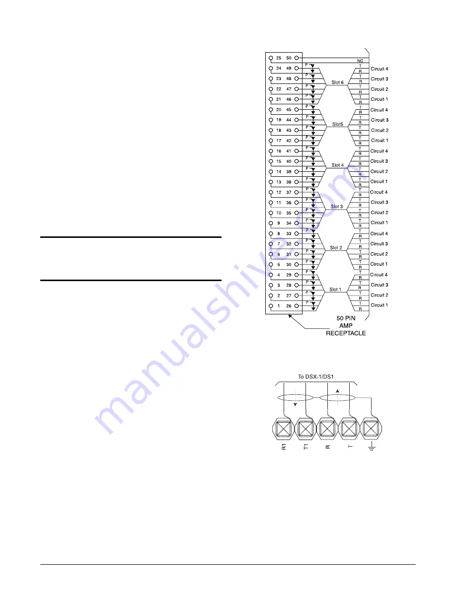
Figure 4. Connector Pinout
Figure 5. T1 Connections
CAUTION
During installation, power should be the last
connection made after all other wire-wrap
connections are completed.


