Chapter 2. Installation
61200610L2-1
TSU 610 User Manual
2-3
IDENTIFICATION OF REAR PANEL LAYOUTS
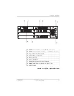
Figure 2-1, Figure 2-2, Figure 2-3, and Figure 2-4 show the
configuration for the rear panels of the TSU 610, TSU 610
with DC Power, TSU 610 HDSL, and TSU 610 HDSL with DC
power.
Figure 2-1. TSU 610 Rear Panel
1
2
3
4
5
6
8
9
10
7
1
T1 Network Connection (DA-15 Connector)
2
T1 Network Connection (RJ-48C)
3
T1 Monitor/Test Jacks
4
Control In/Out Connection
5
Alarm Relay Connection
6
Power Switch
7
1A/250V Fuse
8
Blank panel covering an unused option slot
9
Example of option modules installed
10 Power Cord
Summary of Contents for 1200610L2
Page 20: ...Table of Contents xx TSU 610 User Manual 61200610L2 1...
Page 24: ...List of Tables xxiv TSU 610 User Manual 61200610L2 1...
Page 56: ...Chapter 3 Operation 3 12 TSU 610 User Manual 61200610L2 1...
Page 94: ...Chapter 4 T1 Network Interface 4 38 TSU 610 User Manual 61200610L2 1...
Page 142: ...Appendix B Understanding TR 08 B 4 TSU 610 User Manual 61200610L2 1...
Page 156: ...Appendix E Specifications E 4 TSU 610 User Manual 61200610L2 1...
Page 168: ......

