background image

 Physical Description

NetVanta 4660/5660 Series

 14

Copyright © 2019 ADTRAN, Inc.

617004660F1-34B

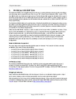
The 

GIG 0/2

 through 

GIG 0/5

 ports consist of one RJ-45 and one SFP slot for connectivity over 

fiber. (Use either the RJ-45 connector 

or

 the SFP slot. The fiber slot has precedence.) See 

Table A-3 on page 32

 for the Ethernet interface pinouts. The status LEDs, are located above 

each interface.

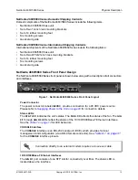
1 PPS 50 ohm Phase Synchronization Measurement Interface

The phase synchronization interface, labeled 

1 PPS OUT

, provides a one pulse per second 

output which can be used to connect to measurement equipment.

• Period: 1 /-1 ppm
• Pulse Width: 200 ns (minimum), 500 ms (maximum), 10 us (typical)
• Rise Time: 5 ns (maximum)
• Voh: 5.5 V (maximum), 1.2 V (minimum)
• Vol: 0.3 V (maximum), -0.3 V (minimum)

Timing Interface

The RJ-45 interface, labeled 

T4

, is provided for timing output in both T12 and E12 modes.

Option Slot

The option slot accepts a variety of network modules (refer to 

Option Modules on page 19

).

LED Descriptions

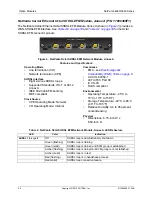
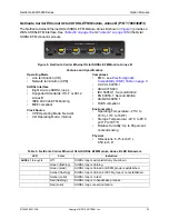
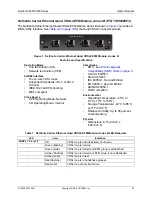
The following table describes LED activity for the NetVanta 4660/5660 Series.

Table 1.  Front Panel Status LED Behaviors

STAT

Off

Unit is not receiving power.

Green (flashing)

The unit is powering up. On power up the 

STAT

 LED flashes 

rapidly for five seconds, during which time the user can escape 

to boot mode from the 

CONSOLE

 port. 

Green (solid)

The power is on and self-test passed.

Red (solid)

The power is on, but the self-test failed or the application code 

could not be booted.

STAT

Off

Unit is not receiving power.

FAN

Green (solid)

Both fans are functioning properly.

Amber (solid)

Only one fan is functioning.

Red (solid)

Neither fan is functioning.

GIG 0/1 

through 

GIG 0/5

Off

Port is inactive or administratively disabled.

Green (solid)

The link is up.

Amber (flashing)

There is activity on the link.

LED

Color

Indication

Summary of Contents for 17406368F1

Page 1: ...1 NetVanta Carrier Ethernet Quad SHDSL EFM Module Annex A 17406368F3 NetVanta Carrier Ethernet Quad SHDSL EFM Module Annex B 17806368F1 NetVanta Carrier Ethernet Octal SHDSL EFM Module Annex A 17806368F3 NetVanta Carrier Ethernet Octal SHDSL EFM Module Annex B 17406369F1 NetVanta Carrier Ethernet Quad VDSL2 EFM Module Annex A 17406369F3 NetVanta Carrier Ethernet Quad VDSL2 EFM Module Annex B 61700...

Page 2: ...ication Software Licensing Agreement Each ADTRAN product contains a single license for ADTRAN supplied software Pursuant to the Licensing Agreement you may a use the software on the purchased ADTRAN device only and b keep a copy of the software for backup purposes This Agreement covers all software installed on the system as well as any software available on the ADTRAN website In addition certain ...

Page 3: ...right 2019 ADTRAN Inc 3 Conventions Warnings provide information that could prevent injury or endangerment to human life Cautions signify information that could prevent service interruption or damage to the equipment Notes provide additional useful information ...

Page 4: ...explode Check with local codes for special disposal instructions 5 The socket outlet shall be installed near the equipment and shall be easily accessible If any of the following conditions occur unplug the product from the electrical outlet and replace the part or contact your qualified service personnel Additional safety guidelines such as Waste Electrical and Electronic Equipment WEEE are given ...

Page 5: ...warranty information The telephone company may require this equipment to be disconnected from the network until the problem is corrected or it is certain the equipment is not malfunctioning 5 This unit contains no user serviceable parts 6 This equipment is designed to connect to the telephone network or premises wiring using an FCC compatible modular jack which is compliant with Part 68 and requir...

Page 6: ...Carrier Ethernet Quad VDSL2 EFM Module Annex A FCC Part 15 Class B EN 300 386 FCC Part 15 Class B EN 300 386 17406369F3 Carrier Ethernet Quad VDSL2 EFM Module Annex B FCC Part 15 Class B EN 300 386 FCC Part 15 Class B EN 300 386 Industry Canada Compliance Information This product meets the applicable Industry Canada technical specifications The Ringer Equivalence Number REN is an indication of the...

Page 7: ... securing your telecommunication and networking equipment rests with you and you are encouraged to review documentation regarding available security measures their configuration and implementation and to test such features as is necessary for your network Third Party Software The software included in this product contains copyrighted software that is licensed under the GNU General Public License G...

Page 8: ...0 15 Physical Interfaces 15 Security 16 DSL Features 17 Ethernet Features 17 Fault and Performance Management 17 Environment 18 Physical and Input Power 18 Agency Approvals 18 Option Modules 19 Network Modules 20 Unit Installation 26 Tools Required 26 Mounting Options 27 Connecting Ground to the Unit 29 Supplying Power to the Unit 29 Installing Network Modules 29 Appendix A Connector Pin Definitio...

Page 9: ...etVanta Carrier Ethernet Quad SHDSL EFM Module Annex B 21 Figure 4 NetVanta Octal SHDSL EFM Network Module Annex A 22 Figure 5 NetVanta Carrier Ethernet Octal SHDSL EFM Module Annex B 23 Figure 6 NetVanta Carrier Ethernet Quad VDSL2 EFM Module Annex A 24 Figure 7 NetVanta Carrier Ethernet Quad VDSL2 EFM Module Annex B 25 Figure 8 Wallmount Installation 28 Figure 9 Network Module Installation 30 ...

Page 10: ...nta Carrier Ethernet Octal SHDSL EFM Module Annex B LED Behaviors 23 Table 6 NetVanta Carrier Ethernet Quad VDSL EFM Module Annex A LED Behaviors 24 Table 7 NetVanta Carrier Ethernet Quad VDSL2 EFM Module Annex B LED Behaviors 25 Table A 1 CONSOLE Port Pinouts 31 Table A 2 SFP Slot Pinouts 31 Table A 3 1000Base T Gigabit Ethernet Port Pinouts 32 Table A 4 T4 Port Pinouts 32 Table A 5 Quad SHDSL EF...

Page 11: ...page 26 For additional information on shipping contents mounting options network module installation and power the unit refer to the following sections Shipping Contents on page 12 Mounting Options on page 27 Supplying Power to the Unit on page 29 Installing Network Modules on page 29 For information on NetVanta 4660 5660 Series configuration for a specific application refer to the configuration g...

Page 12: ...anta 4660 5660 will continue to operate on the remaining loop providing redundancy Once the failed loop is operational again the NetVanta 4660 5660 will automatically detect its availability and will automatically recover to the original configuration Network Modules Supported The main base unit supports interchangeable network modules The network modules currently available in this series include...

Page 13: ... interfaces T4 48VDC GIG 0 1 STAT FAN GIG 0 2 GIG 0 3 GIG 0 4 GIG 0 5 CONSOLE NetVanta 4660 1 PPS OUT Figure 1 NetVanta 4660 5660 Series Front Panel Layout Power Connector The power connector labeled 48VDC provides connection for a 48 VDC power source Please refer to Supplying Power to the Unit on page 29 for connection details Status LEDs The STAT LED indicates the unit s status The FAN LED refle...

Page 14: ... labeled T4 is provided for timing output in both T12 and E12 modes Option Slot The option slot accepts a variety of network modules refer to Option Modules on page 19 LED Descriptions The following table describes LED activity for the NetVanta 4660 5660 Series Table 1 Front Panel Status LED Behaviors STAT Off Unit is not receiving power Green flashing The unit is powering up On power up the STAT ...

Page 15: ...g Physical Interfaces Ethernet Four 10 100 1000Base T dual copper or SFP and one fiber only SFP for a total of five Gigabit Ethernet interfaces All ports included in chassis All Ethernet interfaces include carrier Ethernet functionality Full duplex RJ 45 connectors Supports 802 1q VLAN trunking Modular WAN Options Quad SHDSL Annex A and B Octal SHDSL Annex A and B Quad VDSL2 Annex A and B Processo...

Page 16: ...tency Queuing Weighted Fair Queuing WFQ and Class based WFQ DiffServ packet marking and recognition Frame Relay fragmentation Traffic monitoring NetFlow 9 Security Firewall Stateful inspection firewall Denial of service DoS protection Access control lists ACLs Application level gateways ALGs Network Address Translation Network address translation NAT 1 1 many 1 and 1 1 port translation NAT compati...

Page 17: ...ority Supports eight class of service CoS queues Per UNI port CE VLAN ID C Tag and or CE VLAN P bits DSCP fields Single stack VLAN and double stack VLANs Q in Q Manipulation based on 802 1p and DSCP fields STAG TPID provisioning supports 802 1ad and802 1Q standards Port based service support Services Scale and Flexibility Configurable EtherType and TPID for service flexibility VLAN IDs 2 to 4090 E...

Page 18: ... 40 F to 185 F Relative Humidity Up to 95 percent noncondensing Physical and Input Power Chassis 1U high 19 inch or 23 inch rack mountable metal enclosure Dimensions 1st Gen 4660 5660 1 72 inch H x 17 22 inch W x 11 5 inch D Dimensions 2nd Gen 4660 5660 1 72 inch H x 17 22 inch W x 8 66 inch D Input Voltage 48 VDC Agency Approvals FCC Part 15 Class B UL 60950 1 Second Edition EN 60950 Second Editi...

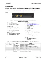
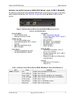
Page 19: ... Module Annex A P N 17406368F1 on page 20 NetVanta Carrier Ethernet Quad SHDSL EFM Module Annex B P N 17406368F3 on page 21 NetVanta Carrier Ethernet Octal SHDSL EFM Module Annex A P N 17806368F1 on page 22 NetVanta Carrier Ethernet Octal SHDSL EFM Module Annex B P N 17806368F3 on page 23 NetVanta Carrier Ethernet Quad VDSL2 EFM Module Annex A P N 17406369F1 on page 24 NetVanta Carrier Ethernet Qu...

Page 20: ...ant Clock Source CPE Operating Mode Network CO Operating Mode Internal Compliance EMC see Electromagnetic Compatibility EMC Table on page 6 UL CUL 60950 1 ACTA FCC Part 68 IC CS 03 RoHS compliant Environmental Operating Temperature 25 C to 70 C 13 F to 158 F Storage Temperature 40 C to 85 C 40 F to 185 F Relative Humidity Up to 95 percent noncondensing Physical Dimensions 6 75 inch W x 6 59 inch D...

Page 21: ...Network CO Operating Mode Internal Compliance EMC see Electromagnetic Compatibility EMC Table on page 6 UL CUL 60950 1 AS ACIF S043 IEC 60950 1 Second Edition EN 60950 1 Second Edition AS NZS 60950 1 RoHS compliant Environmental Operating Temperature 25 C to 70 C 13 F to 158 F Storage Temperature 40 C to 85 C 40 F to 185 F Relative Humidity Up to 95 percent noncondensing Physical Dimensions 6 75 i...

Page 22: ... MEF compliant Clock Source CPE Operating Mode Network CO Operating Mode Internal Compliance EMC see Electromagnetic Compatibility EMC Table on page 6 UL CUL 60950 1 ACTA FCC Part 68 IC CS 03 RoHS compliant Environmental Operating Temperature 25 C to 70 C 13 F to 158 F Storage Temperature 40 C to 85 C 40 F to 185 F Relative Humidity Up to 95 percent noncondensing Physical Dimensions 6 75 inch W x ...

Page 23: ...CPE Operating Mode Network CO Operating Mode Internal Compliance EMC see Electromagnetic Compatibility EMC Table on page 6 UL CUL 60950 1 AS ACIF S043 IEC 60950 1 Second Edition EN 60950 1 Second Edition AS NZS 60950 1 RoHS compliant Environmental Operating Temperature 25 C to 70 C 13 F to 158 F Storage Temperature 40 C to 85 C 40 F to 185 F Relative Humidity Up to 95 percent noncondensing Physica...

Page 24: ...urce CPE Operating Mode Network CO Operating Mode Internal Compliance EMC see Electromagnetic Compatibility EMC Table on page 6 UL CUL 60950 1 ACTA FCC Part 68 IC CS 03 RoHS compliant Environmental Operating Temperature 25 C to 70 C 13 F to 158 F Storage Temperature 40 C to 85 C 40 F to 185 F Relative Humidity Up to 95 percent noncondensing Physical Dimensions 6 75 inch W x 6 59 inch D Table 6 Net...

Page 25: ...ork CO Operating Mode Internal Compliance EMC see Electromagnetic Compatibility EMC Table on page 6 UL CUL 60950 1 AS ACIF S043 IEC 60950 1 Second Edition EN 60950 1 Second Edition AS NZS 60950 1 RoHS compliant Environmental Operating Temperature 25 C to 70 C 13 F to 158 F Storage Temperature 40 C to 85 C 40 F to 185 F Relative Humidity Up to 95 percent noncondensing Physical Dimensions 6 75 inch ...

Page 26: ...Required The customer provided tools required for the hardware installation of the NetVanta are To access the CLI of the NetVanta you will also need a PC with terminal emulation software and a console port cable Instructions on how to access the CLI are available in the quick start guide shipped with your unit or online at ADTRAN s Support Forum Ethernet cables Network cables module dependent Phil...

Page 27: ...screwdriver 5 Apply power to the unit refer to Supplying Power to the Unit on page 29 If installed in a closed or multi unit rack assembly the operating ambient temperature of the rack environment may be greater than room ambient temperature Therefore consideration should be given to installing the equipment in an environment compatible with the maximum ambient temperature specified by the manufac...

Page 28: ...o a stud ensures stability Using sheetrock anchors may not provide sufficient long term stability 4 Have an assistant hold the unit in position as you install two 6 to 10 1 inch or greater in length wood screws through the unit s brackets and into the mounted board see Figure 8 on page 28 5 Proceed to the steps given in Connecting Ground to the Unit on page 29 and Supplying Power to the Unit on pa...

Page 29: ...ource Installing Network Modules The network modules are installed into the front panel option module slot The following table lists the installation steps Also see Figure 9 on page 30 For NetVanta modules with outside plant connections ensure that all cables are removed from the module before installing or removing it from the NetVanta chassis Use a reliably grounded 48VDC SELV source Use a branc...

Page 30: ...and connected to the network For information on configuration for a specific application refer to the configuration guides provided online on ADTRAN s Support Forum For details on the CLI refer to the AOS Command Reference Guide All other related documents are also available online on ADTRAN s Support Forum Electronic modules can be damaged by static electrical discharge Before handling modules pu...

Page 31: ...Data output 3 TD Transmit Data input 4 DTR Data Terminal Ready input 5 SG Signal Ground 6 DSR Data Set Ready output 7 RTS Request to Send input 8 CTS Clear to Send output 9 Unused 1 TGND 11 RGND 2 TX FAULT 12 RX 3 TX DISABLE 13 RX 4 MOD DEF 2 14 RGND 5 MOD DEF 1 15 VccR 6 MOD DEF 0 16 VccT 7 RATE SELECT 17 TGND 8 LOS 18 TX 9 RGND 19 TX 10 RGND 20 TGND Table A 1 CONSOLE Port Pinouts Pin Name Descri...

Page 32: ...ive 7 TRD3 Transmit Receive Positive 8 TRD3 Transmit Receive Negative Description 1 3 Unused 4 R Transmit data toward the network Ring 5 T Transmit data toward the network Tip 6 Unused 7 GND Ground 8 Unused Appendix A NetVanta 4660 5660 Series 32 Copyright 2019 ADTRAN Inc 617004660F1 34B Table A 3 1000Base T Gigabit Ethernet Port Pinouts Pin Name Description Table A 4 T4 Port Pinouts Pin Name ...

Page 33: ... Loop 3 Tip 5 R01 Loop 1 Ring 5 R03 Loop 3 Ring 6 8 Unused 6 8 Unused 1 T06 Loop 6 Tip 1 T08 Loop 8 Tip 2 R06 Loop 6 Ring 2 R08 Loop 8 Ring 3 Unused 3 Unused 4 T05 Loop 5 Tip 4 T07 Loop 7 Tip 5 R05 Loop 5 Ring 5 R07 Loop 7 Ring 6 8 Unused 6 8 Unused Table A 5 Quad SHDSL EFM Pinouts Ports 1 and 2 Ports 3 and 4 Pin Name Description Pin Name Description Table A 6 Octal SHDSL EFM Ports 1 through 4 Pin...

Page 34: ...Unused 3 Ring Ring lead of the 2 wire interface 4 Tip Tip lead of the 2 wire interface 5 6 Unused Appendix A NetVanta 4660 5660 Series 34 Copyright 2019 ADTRAN Inc 617004660F1 34B Table A 8 Quad VDSL2 Pinouts Pin Name ...

Reviews: