5
61190851L2-5, Issue 3
61190851L2-5C
3. TESTING
Testing Line Units
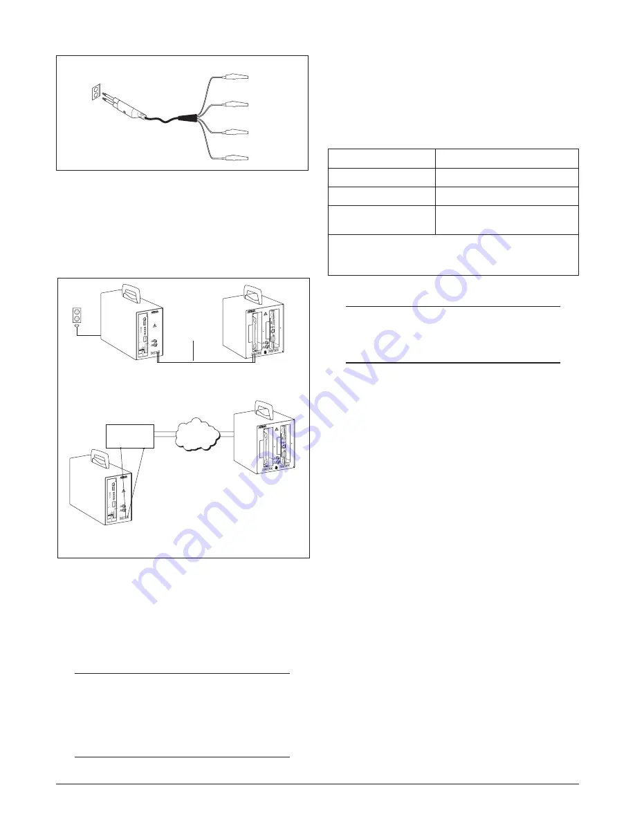
This section describes the method for testing HDSL
line units (See
Figure 6
).
2. Verify that the other required line units are available
for the test (see
Table 1
). The required line unit(s)
can either be installed in another HDSL Installation
Kit, or in an HDSL circuit.
NOTE
Verify that the required line units are operational
before proceeding.
3. Install patch cables to make the necessary
connections between the line unit being tested
and the required line units.
If the required line unit(s) is installed in another
HDSL Installation Kit, install patch cables between
the LP1/LP2 signal jacks on each HDSL Installation
Kit. If the required line unit(s) is in the HDSL circuit,
install patch cables between the HDSL Installation
Kit’s LP1/LP2 signal jacks and the HDSL circuit’s
loop 1 and loop 2 twisted pairs.
4. If a repeater line unit is being tested, or if the
operation of a CO line unit is being tested with a
repeater, place the repeater selection button on
the remote unit IN. To perform the test without
the repeater, place the repeater button OUT on
the Remote Installation Kit.
5. When power is applied, the HDSL Installation
Kit tests the operation of the line unit.
Observe LED indication on the line unit front panel to
determine whether the line unit is operational.
Loop 1
Loop 2
Red
Loop 1 (T)
Loop 1 (R)
Loop 2 (T)
Loop 2 (R)
Green
Yellow
Black
Figure 5. Test Cable
Figure 6. Testing HDSL Live Units
CAUTION:
RISK OF ELEC
TRICAL
SHOCK. MAX
IMUM
VOLTAGES UP
TO
-200 VDC MA
Y BE
PRESENT ON
TELECOM
CIRCUITS.
1190852L2
HDSL 852 CO
POWER
REMOTE
LP1 LP2
DS1
TX RX
ESD
GND
DSX-1
LBO
B8ZS
FRM
ESF
NIU LB DIS
LB TIMEOUT
DIS
533
399
266
133
0
EXT
124600
1L2
LBK
ALM
DSX
DSL
TX
RX
TX
RX
M
O
N
E
Q
HTU-C
M
AMI
UFRM
SF
EN
EN
12
34
5
Patch
Cables
CO Line Unit Being
Tested
115 VAC
Known Good CO
Line Unit
Remote Line Unit
Being Tested
Known Good Remote
Line Unit
Distribution
Frame
HDSL
Circuit
CAUTION:
RISK OF ELECT
RICAL
SHOCK. MAXI
MUM
VOLTAGES UP
TO
-200 VDC MAY
BE
PRESENT ON T
ELECOM
CIRCUITS.
1190851L2
HDSL 851 REP
EATER/ REMOT
E
ESD
GND
RPTR. C.O.
CABLE PAIRS
RPTR. TO REMOT
E
CABLE PAIRS
LP1 LP2
LP1 LP2
REMOTE
CABLE PAIRS
DS1
LP1 LP2
LP1 LP2
RPTR
IN
OUT
HRE
1246041
L1
PWR
LP1
LP2
LP1
LP2
LBK
CAUTION:
RISK OF ELECT
RICAL
SHOCK. MAXI
MUM
VOLTAGES UP
TO
-200 VDC MAY
BE
PRESENT ON T
ELECOM
CIRCUITS.
1190851L2
HDSL 851 REP
EATER/ REMOT
E
ESD
GND
RPTR. C.O.
CABLE PAIRS
RPTR. TO REMOTE
CABLE PAIRS
LP1 LP2
LP1 LP2
REMOTE
CABLE PAIRS
DS1
LP1 LP2
LP1 LP2
RPTR
IN
OUT
HRE
1246041
L1
PWR
LP1
LP2
LP1
LP2
LBK
d
e
t
s
e
T
g
n
i
e
B
ti
n
U
e
n
i
s
L
ti
n
U
e
n
i
L
d
e
r
i
u
q
e
R
l
a
n
o
it
i
d
d
A
ti
n
u
e
n
il
O
*
C
ti
n
u
e
n
il
e
t
o
m
e
R
ti
n
u
e
n
il
e
t
o
m
e
*
R
ti
n
u
e
n
il
O
C
ti
n
u
e
n
il
r
e
t
a
e
p
e
t
R
i
n
u
e
n
il
O
C
ti
n
u
e
n
il
e
t
o
m
e
R
o
s
l
a
s
i
ti
n
u
e
n
il
r
e
t
a
e
p
e
r
a
,r
e
t
a
e
p
e
r
a
h
ti
w
n
o
it
a
r
e
p
o
t
s
e
t
o
T
*
.
d
e
ri
u
q
e
r
.
y
l
e
t
a
r
a
p
e
s
d
e
s
a
h
c
r
u
p
e
r
a
s
ti
n
u
e
n
il
ll
A
:
e
t
o
N
Table 1. Line Units
The steps are as follows:
1. Install the line unit to be tested in the appropriate
HDSL Installation Kit.
CAUTION
Before handling line units, make sure the HDSL
Installation Kit is connected to earth ground and
the ESD wrist strap is connected to the installation
kit.


