background image

7

61190851L2-5, Issue 3

61190851L2-5C

1. Install an HDSL remote line unit in the HDSL

Installation Kit.  Make sure the HDSL assistant is

connected to ground, and the ESD wrist strap is

connected to the Installation Kit.

2. Install a test cable to make the following

connections.  Be sure to maintain signal polarity

with the test cable.

• Connect the remote LP1 signal jack to the

loop 1 twisted pair.

• Connect the remote LP2 signal jack to the

loop 2 twisted pair.

3. When power is applied to the HDSL circuit, the

HDSL Installation Kit can be used to test remote

line units, or the LP1/LP2 signal jacks can be

used to access the circuit’s loop 1 and loop 2

signals.

T1 BERT Testing of an HDSL Circuit

This section describes how to perform a T1 Bit Error

Rate Test (BERT) using an HDSL Installation Kit and

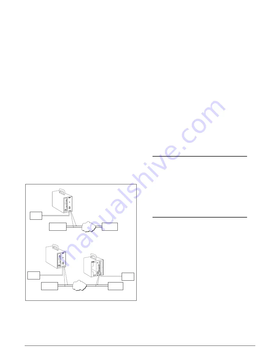
a T1 BERT tester (See 

Figure 9

).

With a single HDSL Installation Kit and T1 BERT

tester, a loopback test of the cable span can be

performed from the central office end or from the

remote end.

With CO and Remote HDSL Installation Kits and two

BERT testers, an end-to-end test of the entire cable

span can be performed.  The directions for performing

the BERT test are as follows.

1. Install test cables to make the following

connections between the T1 BERT tester and the

HTU-C installed in the HDSL Installation Kit.

For an end-to-end test, make the connections at

both ends of the cable span.
• Connect the BERT tester’s DSX-1 RX jack to

the DS1 line receive jack on the front panel of

the HTU-C or HTU-R

• Connect the BERT testers DSX-1 TX jack to

the DS1 line transmit jack on the front panel

of the HTU-C or HTU-R.

NOTE

As an alternative to the DS1 signal jacks, use the

DS1 RX and TX jacks located just above the line

unit slot on the HDSL Installation Kit.  These

jacks correspond to line unit operation, which

means that the BERT tester’s DS1 transmit jack

must be connected to the installation kit’s DS1

TX jack, and the tester’s DS1 receive jack to the

installation kit’s DS1 RX jack.

2. Install a test cable to connect the HDSL

Installation Kit to the HDSL circuit.  For an

end-to-end test, make the connections at both

ends of the cable span.
• Connect the HDSL Installation Kit LP1

signal jack to the loop 1 twisted pair.

• Connect the HDSL Installation Kit LP2

signal jack to the loop 2 twisted pair.

3. If a loopback BERT test is being performed, loop

back the far end.

4. Turn ON the HDSL Installation Kit and T1

BERT tester.  If an end-to-end test is being run,

turn on both Installation Kits and testers.

5. Run a T1 BERT test over the HDSL cable span.

Figure 9.  T1 BERT Testing of an HDSL Circuit

Remote/Repeater Shelf

End-to-End BERT

Serving Office

DS1 Receive

DS1 Transmit

Central Office Powering Shelf

LP1/LP2

LP1/LP2

Customer

Equipment

HDSL

Circuit

CAUTION:

RISK OF ELECT

RICAL

SHOCK.  MAXI

MUM

VOLTAGES UP T

O

-200 VDC MAY

 BE

PRESENT ON T

ELECOM

CIRCUITS.

1190851L2

HDSL 851 REP

EATER/ REMOT

E

ESD

GND

RPTR. C.O.

CABLE PAIRS

RPTR. TO REMOT

E

CABLE PAIRS

LP1 LP2

LP1 LP2

REMOTE

CABLE PAIRS

DS1

LP1 LP2

RX TX

RPTR

IN

OUT

T1 BERT

Tester

CAUTION:

RISK OF ELEC

TRICAL

SHOCK.  MAX

IMUM

VOLTAGES UP

 TO

-200 VDC MA

Y BE

PRESENT ON T

ELECOM

CIRCUITS.

1190852L2

HDSL 852 CO

 POWER

REMOTE

LP1 LP2

DS1

TX RX

ESD

GND

DSX-1

LBO

B8ZS
FRM
ESF

NIU LB DIS

LB TIMEOUT

 DIS

533

399

266

133

0

EXT

1246001L

2

LBK

ALM

DSX

DSL

TX

RX

TX

RX

M

O

N

E

Q

HTU-C

M

AMI
UFRM
SF
EN
EN

1234

5

T1 BERT

Tester

DS1 Receive

DS1 Transmit

Serving Office

T1 BERT

Tester

DS1 Receive

DS1 Transmit

Central Office Powering Shelf

Loopback BERT

LP1/LP2 Signals

HDSL

Circuit

CAUTION:

RISK OF ELEC

TRICAL

SHOCK.  MAX

IMUM

VOLTAGES UP

 TO

-200 VDC MA

Y BE

PRESENT ON T

ELECOM

CIRCUITS.

1190852L2

HDSL 852 CO

 POWER

REMOTE

LP1 LP2

DS1

TX RX

ESD

GND

DSX-1

LBO

B8ZS
FRM
ESF

NIU LB DIS

LB TIMEOUT

 DIS

533

399

266

133

0

EXT

1246001L

2

LBK

ALM

DSX

DSL

TX

RX

TX

RX

M

O

N

E

Q

HTU-C

M

AMI
UFRM
SF
EN
EN

1234

5

Remote End

Loopback

Summary of Contents for HDSL 851

Page 1: ...ion unit Optional adapter for 239 439 size repeaters Span powered Connections for local power Bantam to alligator connections Adapter Insert A separately purchased adapter insert configures the T200 400 form factor to accommodate the following mechanics Insert T200 400 to 239 439 form factor P N 1190851L22 Figure 1 HDSL 851 Remote Installation Shelf TABLES Table 1 Line Units 5 Table 2 Specificatio...

Page 2: ...ge is noted file a claim with the carrier then notify ADTRAN See Warranty and Customer Service The Remote Installation Kit is shipped complete with remote shelf and dual bantam to alligator cables Front Panel Features The HDSL Remote Installation Kit front panel features remote and repeater unit slots four dual bantam jacks a repeater selection button and two ground lugs for ESD ground and earth g...

Page 3: ...ring is not available the unit can be locally powered by applying 48 Vdc to connectors on the back of the unit Preventing ESD Damage To prevent damage caused by electrostatic discharge ESD follow these precautions when using the HDSL Installation Kit 1 Install the ground cable between ground and the bottom ground lug on the front of the HDSL Installation Kit 2 When working with HDSL line units mak...

Page 4: ...L circuit 4 To remove an HTU R remove the patch cord connecting the line unit to the HDSL circuit Pull the ejector lever on the bottom of the HTU R or grasp the line unit by its front panel and gently pull it from the slot observing ESD precautions Installing Test Cables The HDSL Installation Kit is connected to the HDSL circuit by installing test cables between the installation kit s LP1 and LP2 ...

Page 5: ...01 L2 LBK ALM DSX DSL TX RX TX RX M O N E Q HTU CM AMI UFRM SF EN EN 1 2 3 4 5 CAUTION RISKOFELECTRICAL SHOCK MAXIMUM VOLTAGES UPTO 200 VDCMAYBE PRESENTONTELECOM CIRCUITS 1190852L2 HDSL852 COPOWER REMOTE LP1 LP2 DS1 TX RX ESD GND DSX 1 LBO B8ZS FRM ESF NIU LB DIS LB TIMEOUT DIS 533 399 266 133 0 EXT 1246001 L2 LBK ALM DSX DSL TX RX TX RX M O N E Q HTU CM AMI UFRM SF EN EN 1 2 3 4 5 Patch Cables CO...

Page 6: ...1190851L2 HDSL 851 REPEATER REM OTE ESD GND RPTR C O CA BLE P AIR S RPT R TOREMOTE CA BLEPA IRS LP1 LP2 LP1 LP2 REMOTE CA BLE PA IRS D S1 LP1 LP2 LP1 LP2 RPTR IN OUT To perform this procedure access to the cable span at a midpoint such as a cross connect must be obtained The steps are as follows WARNING On a live HDSL circuit potentially dangerous voltage may be present on the loop 1 and loop 2 si...

Page 7: ...the BERT tester s DS1 transmit jack must be connected to the installation kit s DS1 TX jack and the tester s DS1 receive jack to the installation kit s DS1 RX jack 2 Install a test cable to connect the HDSL Installation Kit to the HDSL circuit For an end to end test make the connections at both ends of the cable span Connect the HDSL Installation Kit LP1 signal jack to the loop 1 twisted pair Conn...

Page 8: ... 852 CO Shelf Table 4 provides a list of products for the CO Installation Kit Table 2 Specifications r e w o P e g a t l o V s p m A c d V 8 4 A 2 0 l a t n e m n o r i v n E e r u t a r e p m e t g n i t a r e p O e r u t a r e p m e t e g a r o t S C 0 5 o t 0 F 2 2 1 o t 2 3 C 0 7 o t 0 4 F 8 5 1 o t 0 4 l a c i s y h P n o i s n e m i D t h g i e W 5 h g i h 2 1 7 p e e d 2 1 6 e d i w 2 1 b l...

Page 9: ...ADTRAN Sales Pricing Availability 800 827 0807 ADTRAN Technical Support Pre sales Applications Post sales Technical Assistance 800 726 8663 Standard hours Monday Friday 7 a m 7 p m CST Emergency hours 7 days week 24 hours day ADTRAN Repair CAPS Return for Repair Upgrade 256 963 8722 Repair and Return Address Contact CAPS prior to returning equipment to ADTRAN ADTRAN Inc CAPS Department 901 Explore...

Page 10: ...C 5 2 L 1 5 8 0 9 1 1 6 3 e u s s I 5 2 L 1 5 8 0 9 1 1 6 0 1 ...

Reviews: