Physical Description
NetVanta 6310/6330 Series Hardware Installation Guide
18
Copyright © 2013 ADTRAN, Inc.
61700100G1-34F
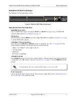
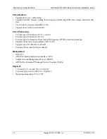
NetVanta 6330 Series Front Panel Design
The NetVanta 6330 front panel is shown below.
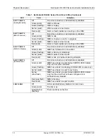
Table 1 on page 19
describes all of the LEDs.
NetVanta 6330 Front Panel Features
Status LEDs
The status LEDs are located on the lower left side of the unit. The
STAT
LED indicates the unit’s
status. The
FXO
LED reflects the status of the FXO interfaces. The
FXS
LED reflects the status of the
FXS interfaces. The
SLOT 1
LED reflects the status of a NIM2/VIM2 installed in NIM2/VIM2 option
SLOT 1
(located on the rear panel). The
LAN 1
and
LAN 2
LEDs reflect the status of the local area
networks (LANs).
CompactFlash Slot
The CompactFlash slot supplies nonvolatile configuration and compressed code storage. CompactFlash
densities from 64 to 1024 MB are supported.
Figure 3. NetVanta 6330 Series Front Panel Layout
NetVanta 6330 Rear Panel Design
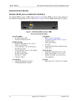
The NetVanta 6330 rear panel is shown below.
Figure 4. NetVanta 6330 Series Rear Panel Layout
NetVanta 6330 Rear Panel Interfaces
VOICE Connector
A single 50-pin female amphenol connector labeled
VOICE
provides the interconnect wiring for up to
24 analog ports. See
Table A-5 on page 44
for the
VOICE
connector pinouts.
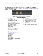
NIM2/VIM2 Option Slot
The NIM2/VIM2 option slot (labeled
SLOT 1
) accepts a variety of NIM2/VIM2 option modules (refer
to
Option Modules on page 23
).
FXO Ports
The two FXO interfaces (labeled
FXO 0/1
and
0/2
) provide FXO connectivity. See
Table A-4 on page
44
for the FXO connector pinouts.
STATUS
FXO
FXS
SLOT 1
LAN 1
LAN 2
NetVanta 6330
CompactFlash
FXO
0/1
0/2
SLOT 1
VOICE
ETH 0/1
ETH 0/2
100-240 VAC
50/60 Hz

