background image

SmartRG Inc., an ADTRAN Company Proprietary and Confidential. All Right Reserved. © 2020

75

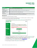
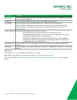
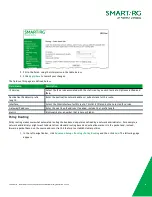
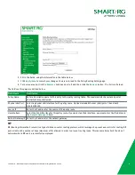
Field Name

Description

Minimum Rate

Enter the minimum shaping rate defined for packets in QoS queues. Options are

1

-

100000

Kbps. The default

is

-1

(no minimum shaping rate).

PTM Priority

Select the priority for this queue. Options are

Low

and

High

. The default is

Low

.

Queue Weight

Enter the weighting value to associate with this queue. Options are

1

-

63

. The default is

1

.

Note:

The higher the weighting value, the more frames that are sent proportionately given the WRR

algorithm employed. Traffic is given priority based on the combined values from this field and the

Precedence

field.

Scheduler Algorithm Select an algorithm for data priority in queues. Options are:

l

Strict Priority

: Allows shaping of rate and burst size for packets in queue.

l

Weighted Round Robin:

Applies a fair round robin scheme weighting that is effective for

networks with fixed packet sizes, e.g., ATM networks.

l

Weighted Fair Queuing:

Applies a fair queuing weighting scheme via allowing different

sessions to have different service shares for improved data packets flow in networks with

variable packet size, e.g., PTM/IP networks.

Shaping Burst Size

Enter the shaping burst size to be applied to packets in the defined queue. Options are

1600 bytes

or

greater.

Shaping Rate

Enter the shaping rate for packets in QoS queues. Options are

1

-

100000

Kbps. The default is

-1

(no minimum

shaping).

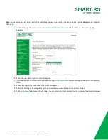
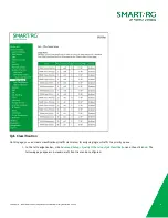
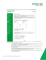
WLAN Queue

On this page, you can view the WLAN queues defined for your network.

Note:

Make sure that wireless connection is active by going to

Wireless

and clicking

Apply/Save

.

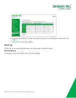
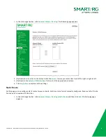
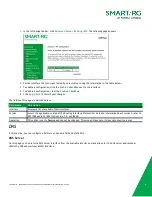
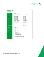
In the left navigation bar, click

Advanced Setup

>

Quality Of Service

>

QoS Queue Config

>

Wlan Queue

. The following page

appears.

Summary of Contents for SMART/RG SR555ac

Page 1: ... Gateway User Manual Model SR555ac Release 1 6 March 2020 Firmware Version 2 6 2 4 501 SE Columbia Shores Boulevard Suite 500 Vancouver Washington 98661 USA 1 360 859 1780 smartrg com ...

Page 2: ... IP Filtering Outgoing 65 IP Filtering Incoming 66 MAC Filtering 68 Parental Control 69 Time Restriction 69 Url Filter 71 Quality of Service 71 Quality of Service 72 QoS Queue 72 QoS Classification 76 QoS Port Shaping 78 Routing 79 Default Gateway 79 Static Route 80 Policy Routing 81 RIP 82 DNS 83 DNS Server 83 Dynamic DNS 85 Static DNS 85 DSL 86 DSL Bonding 88 UPnP 89 DNS Proxy 89 Storage Service...

Page 3: ...137 TR 069 137 STUN Config 139 Internet Time 140 Access Control 141 Services 142 Accounts 143 Passwords 145 Access List 146 Logout Timer 147 Update Software 148 Reboot 149 Logout 150 Appendix FCC Statements 151 FCC Interference Statement 151 FCC Radiation Exposure Statement 151 FCC PART 68 152 Ringer Equivalency Number Statement 152 IC CS 03 statement 152 Canada Statement 152 5GHz 153 Revision His...

Page 4: ...etting Assistance Frequently asked questions are provided at the bottom of the Subscribers page of the SmartRG Web site Subscribers If you require further help with this product please contact your service provider Service providers if you require further help with this product please open a support request Copyright and Trademarks Copyright 2020 by SmartRG Inc Published by SmartRG Inc an ADTRAN c...

Page 5: ...sferred POWER Device in CFE mode Device powered on and ready for use DSL For VDSL only WAN service Single Line Inner or Outer Pair For VDSL only WAN service Bonded Line DSL line 0 acquiring sync DSL line 0 inner pair connected DSL Line 0 Inner pair is active DSL line 1 Outer pair is not active DSL line 1 outer pair acquiring sync and connected DSL Line 1 Outer pair is active DSL line 0 Inner pair ...

Page 6: ...ia a DSL service LAN 1 4 The yellow RJ45 ports can be used to connect client devices such as computers and printers to your gateway WAN The blue RJ45 port is used to hard wire your gateway to another network device For models with both WAN and DSL ports when your Internet connection is via DSL you can configure the WAN port to function as an additional LAN port For detailed instructions see the Et...

Page 7: ...its of the SR555ac gateway these buttons are labeled WiFi instead of 2 4 GHz and WPS instead of 5 GHz These buttons are located on the left side of the gateway and control the Wi Fi radio functions To turn a wireless radio on or off press the related button briefly 1 2 seconds For example to turn the 2 4 GHz radio on or off press the 2 4GHz button for 1 2 seconds To enable WPS press the related bu...

Page 8: ...4 Plug the power adapter to the wall outlet and then connect the other end of it to the Power port of the gateway 5 Turn on the unit by pressing the On Off button on the side of the gateway Note If you use 3G WAN service connect the 3G USB data card to a USB port of the gateway If you use the Ethernet uplink connect to the WAN interface using an Ethernet cable You cannot use the xDSL uplink 3G WAN...

Page 9: ...rs 3 To view the system log for this gateway click View log the top right of the page The log appears in a separate window 4 To log into the GUI click Manage gateway advanced at the top right of the page The login dialog box appears 5 Enter the user name and password The default user name and password of the super user are admin and admin The username and password of the common user are user and u...

Page 10: ...d configure DHCP ARP and WAN interfaces Summary On this page you can view device such as the board ID software version and information about your WAN connection such as the upstream rate and the LAN address When you log into the gateway GUI the Device Info summary page appears You can also reach this page by clicking Device Info Summary in the left navigation menu ...

Page 11: ...on The service identifier such as pppoe_0_1_1 35 Type The service type Options are PPPoE IPoE and Bridge VlanMuxId The VLAN ID Options are Disabled or 0 4094 IPv6 The state of IPv6 Options are Enabled Disabled and N A Igmp Pxy The state of the IGMP proxy Options are Enabled Disabled and N A Igmp Src Enbl The state of the IGMP source Options are Enabled and Disabled MLD Pxy The state of the MLD pro...

Page 12: ...m of the page The fields on this page are defined below Field Name Description Interface Available LAN interfaces Options are LAN1 LAN4 5GHz and 2 4 GHz Received Transmitted columns Bytes The total number of packets in bytes Pkts The total quantity of packets Errs The total quantity of error packets Drops The total quantity of dropped packets WAN Service On this page you can view the received and ...

Page 13: ...tes Pkts The total quantity of packets Errs The total quantity of error packets Drops The total quantity of dropped packets xTM On this page you can view the ATM PTM statistics for your gateway All WAN interfaces configured for your gateway are included In the left navigation bar click Device Info Statistics xTM The Interface Statistics page appears To reset these counters click Reset near the bot...

Page 14: ...eived OAM Cells Out OAM Cells Total quantity of transmitted OAM Cells In ASM Cells Total quantity of received ASM Cells Out ASM Cells Total quantity of transmitted ASM Cells In Packet Errors Total quantity of received Packet Errors In Cell Errors Total quantity of received Cell Errors xDSL On this page you can view the DSL statistics for your gateway All xDSL VDSL or ADSL interfaces configured for...

Page 15: ...hich you want to view statistics or to run an xDSL Bit Error Rate BER test that determines the quality of the xDSL connection Options are line 0 and line 1 3 To run an xDSL BER test follow the instructions in Running xDSL BER tests 4 To reset the counters click Reset Statistics near the bottom of the page The fields on this page are defined below Field Name Description Last Synchronized Time when ...

Page 16: ...e the SNR Target Margin l BER not to exceed the highest BER configured for one or more latency paths l Latency not to exceed the highest latency configured for one or more latency paths l Accounting for all coding gains available e g trellis coding RS FEC with latency bound l Accounting for the loop characteristics at the instant of measurement 2 PhyR Status Visible only for gateways connected via...

Page 17: ...or gateways connected via DSL Total number of Reed Solomon Codewords Uncorrected HEC Errors Count of ATM HEC errors detected As per ITU T G 992 1 and G 992 3 a1 byte HEC is generated for each ATM cell header Error detection is implemented as defined in ITU T I 432 1 with the exception that any HEC error shall be considered as a multiple bit error and therefore HEC Error Correction is not performed...

Page 18: ...SL transceivers 2 ITU T Recommendation G 992 3 2005 Asymmetric digital subscriber line transceivers 2 ADSL2 3 ITU T Recommendation G 997 1 2006 Physical layer management for digital subscriber line DSL transceivers 4 ITU T Recommendation I 432 1 1999 B ISDN user network interface Physical layer specification General characteristics Running xDSL BER tests 1 Scroll to the bottom of the page and clic...

Page 19: ...letes a success dialog box appears Note If the BER reaches e 5 you cannot access the Internet Route On this page you can view the LAN and WAN route table information configured in your gateway for both IPv4 and IPv6 implementation In the left navigation bar click Device Info Route The following page appears ...

Page 20: ...s Subnet Mask For IPv4 only Subnet Masks Next Hop For IPv6 only Identifies the next server in the IPv6 path if any Flag Status of the flags Metric Number of hops to reach the default gateway Service Service type Interface WAN LAN interface ARP On this page you can view the MAC address and IP address information for the devices connected to the gateway In the left navigation bar click Device Info A...

Page 21: ... host is connected Options are br atm eth and ptm DHCP On this page you can view the host name the IP address assigned by the DHCP server the MAC address corresponding to the IP address and the DHCP lease time In the left navigation bar select Device Info DHCP The following screen appears The fields on this page are defined below Field Name Description Hostname Host name of each connected LAN devi...

Page 22: ...cription Hostname Host name of each connected LAN device MAC Address MAC address for each connected LAN device IP Address IP address for each connected LAN device VPN On this page you can view details about the IPSec tunnels configured for your gateway In the left navigation bar select Device Info VPN The following screen appears The fields on this page are defined below Field Name Description Tun...

Page 23: ...de Enabled Indicates whether the tunnel is enabled or disabled Connection State Indicates whether the tunnel connection is active or inactive CPU Memory On this page you can view the CPU and memory data for the gateway In the left navigation bar click Device Info CPU Memory The following page appears showing the current usage and history The information refreshes automatically ...

Page 24: ...re the network interfaces for your gateway ATM Interface On this page you can configure Asynchronous Transfer Mode Permanent Virtual Conduit ATM PVC settings for your gateway You can customize latency options link type encapsulation mode and more Note Devices gateways on both ends of the connection must support ATM PVC 1 In the left navigation bar click Advanced Setup Layer2 Interface ATM Interfac...

Page 25: ...fields on this page are defined below Field Name Description VPI Enter a Virtual Path Identifier A VPI is an 8 bit identifier that uniquely identifies a network path for ATM cell packets to reach its destination A unique VPI number is required for each ATM path This setting works with the VCI Each individual DSL circuit must have a unique VPI VCI combination Options are 0 255 The default is zero 0...

Page 26: ...carry one protocol per PVC l VC MUX Virtual Circuit Multiplexer creates a virtual connection used to carry one protocol per PVC Service Category Select the bit rate protocol Options are l UBR without PCR Unspecified Bit Rate with no Peak Cell Rate flow control or time synchronization between the traffic source and destination Commonly used with applications that can tolerate data packet loss l UBR...

Page 27: ...nt larger packets or more packets per second than the others since it became active will only affect itself and not other sessions Default Queue Weight Enter the default weight of the specified queue Options are 1 63 The default is 1 Default Queue Precedence Enter the precedence of the specified group The lower the value the higher the priority Options are 1 8 The default is 8 VC WRR Weight Enter ...

Page 28: ...ce as the Default Queue Select the algorithm used to schedule queue behavior VC scheduling is different than scheduling done for default queues Options are l Weighted Round Robin Packets are accessed in a round robin style and classes can be assigned Time slices are assigned to each process in equal portions and in circular order handling all processes without priority also known as cyclic executi...

Page 29: ...needed Notes l Only one Ethernet WAN interface is allowed If a WAN port it is already configured you must remove it before you can define a new one Click the Remove checkbox and then click the Remove button The Add button appears when the existing port is removed l If a WAN port is already configured and associated with a WAN service you must remove the WAN service configuration before you can rem...

Page 30: ...ce click Add The following page appears 3 Modify the settings as desired using the information in the topics listed below l PPP over Ethernet WAN Service l IP over Ethernet WAN Service l Bridging 4 To edit an interface a Click the Edit button at the far right b Modify the settings as needed and then click through to click Apply Save 5 To remove an interface click the Remove checkbox next to it and...

Page 31: ...PPoE WAN service You will progress through several pages to complete the configuration Note You can configure 7 services If 7 services are configured you must remove 1 of the services before configuring a new one 1 In the left navigation bar click Advanced Setup WAN Service and then click Add The following page appears 2 Select the Layer 2 interface to use for the WAN service ...

Page 32: ...her fields using the information in the following table Field Name Description Enter Service Description Optional Enter a name to describe this configuration Enter 802 1P Priority Enter the priority for this service Options are 0 7 The default is 1 disabled For tagged service enter values in this field and the 802 1Q VLAN ID field For untagged service accept the defaults of 1 disabled in this fiel...

Page 33: ...ntifier that precedes the VLAN ID value Options are 0x8100 0x88A8 and 0x100 Internet Protocol Selection Different scheduling priorities can be applied to statistically multiplexed data flows Since each data flow has its own queue an ill behaved flow which has sent larger packets or more packets per second than the others will only punish itself and not other sessions Options are IPv4 Only IPv4 IPv...

Page 34: ...SmartRG Inc an ADTRAN Company Proprietary and Confidential All Right Reserved 2020 34 ...

Page 35: ...To disable keepalive packets clear the checkbox Enter values in the following fields l LCP Keepalive Period s Enter the interval for sending echos in seconds The default is 30 seconds l LCP Retry Threshold Enter the number of times that echos should be sent before reporting echo failure The default is 5 times PPP IP Extension Click to forward all traffic to the specified DMZ IP When you select thi...

Page 36: ... enable Session Initiation Protocol SIP pass through NAT Used for Voice over IP VOIP applications Port Control Protocol Mode PCP is a computer networking protocol that allows hosts on IPv4 or IPv6 networks to control how the incoming IPv4 or IPv6 packets are translated and forwarded by an upstream router that performs network address translation NAT or packet filtering Options are Disable DS Lite ...

Page 37: ...ress for a single WAN interface 8 Click Next The following page appears where you will select the interface used as a default gateway used for the PPP service being created 9 Click the arrows to move your selections from left to right or from right to left 10 Optional For IPv6 environments in the Selected WAN Interface field select the preferred WAN interface for the default IPv6 gateway ...

Page 38: ...e following to configure the DNS l Select the DNS server interface Select interface entries and click the arrows to move the entries right or left l Define a static DNS IP address Click Use the following Static DNS IP address and enter the DNS server IP addresses l Obtain IPv6 DNS info from a WAN interface In the Obtain IPv6 DNS info from a WAN interface field select a WAN interface ...

Page 39: ... PPPoE WAN setup is complete 14 Review the summary and either click Apply Save to commit your changes or click Back to step through the pages in reverse order to make any necessary alterations IP over Ethernet WAN Service There are several parts to configuring an IP over Ethernet IPoE WAN service You will progress through several pages to complete the configuration Before you can configure a WAN s...

Page 40: ...SmartRG Inc an ADTRAN Company Proprietary and Confidential All Right Reserved 2020 40 1 In the left navigation bar click Advanced Setup WAN Service and then click Add The following page appears ...

Page 41: ...ion Optional Enter a name to describe this configuration Enter 802 1P Priority Options are 0 7 The default is 1 disabled For tagged service enter values in this field and the 802 1Q VLAN ID field For untagged service accept the defaults of 1 disabled in this field and the 802 1Q VLAN ID field Enter 802 1Q VLAN ID Options are 0 4094 The default is 1 disabled For tagged service enter values in this ...

Page 42: ...net Protocol Selection Different scheduling priorities can be applied to statistically multiplexed data flows Since each data flow has its own queue an ill behaved flow which has sent larger packets or more packets per second than the others will only punish itself and not other sessions Options are IPv4 Only IPv4 IPv6 Dual Stack and IPv6 Only Note When you select IPV4 IPV6 or IPV6 the options pre...

Page 43: ...SmartRG Inc an ADTRAN Company Proprietary and Confidential All Right Reserved 2020 43 5 Click Next The following page appears ...

Page 44: ...ss is not available the DHCP server assigns the next allowed IP address Option 51 Request Leased Time Enter the maximum lease time defined for the client The default is zero 0 Option 54 Request Server Address Enter the IP address of the source server Use the following Static IP address Click to manually declare the static IP information provided by your ISP When you select this option you must ent...

Page 45: ...ption clear the checkbox Use the following Static IPv6 address Select this option to manually declare the v6 Static IP information provided by your ISP WAN IPv6 Address Prefix Length Available only when Static IPv6 address is selected If entering a static IP address enter the IP address prefix length If you do not specify a prefix length the default of 64 is used WAN Next Hop IPv6 address Availabl...

Page 46: ...work LAN If you do not want to enable NAT atypical and wish the user of this gateway to access the Internet normally you need to add a route on the uplink equipment Failure to do so will cause access to the Internet to fail The fields on this page are defined below FIELD NAME DESCRIPTION Enable NAT This option is selected by default Click to disable sharing the WAN interface across multiple device...

Page 47: ...tworking protocol that allows hosts on IPv4 or IPv6 networks to control how the incoming IPv4 or IPv6 packets are translated and forwarded by an upstream router that performs network address translation NAT or packet filtering Options are Disable DS Lite and NAT444 The default is Disable PCP Server Enter the server name to be used with PCP IGMP Multicast settings section Enable IGMP Multicast Prox...

Page 48: ...d 2020 48 9 Click Next The following page appears 10 Select a WAN interface to act as the system default gateway or accept the default interface 11 Optional For IPv6 environments in the Selected WAN Interface field select the preferred WAN interface for the default IPv6 gateway ...

Page 49: ...SmartRG Inc an ADTRAN Company Proprietary and Confidential All Right Reserved 2020 49 12 Click Next The following page appears 13 Modify the settings as needed ...

Page 50: ...2020 50 14 Click Next The following page appears 15 Review the IPoE settings You can modify the settings by clicking the Back button 16 Click Apply Save to save and apply the settings Bridging Before you can configure a bridge WAN service you must create the related ATM interface ...

Page 51: ...SmartRG Inc an ADTRAN Company Proprietary and Confidential All Right Reserved 2020 51 1 In the left navigation bar click Advanced Setup WAN Service and then click Add The following page appears ...

Page 52: ...iption Allow as IGMP Multicast Source Select to enable this service to act as an IGMP multicast source Allow as MLD Multicast Source Select to enable this service to act as an MLD multicast source Enter Service Description Optional Enter a different name to describe this configuration Enter 802 1P Priority Options are 0 7 The default is 1 disabled For tagged service enter values in this field and ...

Page 53: ...ears indicating that your Bridging WAN setup is complete 6 Review the summary and either click Apply Save to commit your changes or click Back to step through the pages in reverse order to make any necessary alterations LAN In this section you can configure an IP address for the DSL gateway enable IGMP snooping enable or disable the DHCP server edit the DHCP options configure the DHCP advanced set...

Page 54: ...ll only be forwarded to ports identified as members of the specific multicast group or groups If you enable the DHCP server the clients will automatically acquire the IP address from the DHCP server If the DHCP server is disabled you need to manually set the start IP address end IP address and the lease time for the clients in the LAN ...

Page 55: ...SmartRG Inc an ADTRAN Company Proprietary and Confidential All Right Reserved 2020 55 IPv4 Autoconfig 1 In the left navigation menu click Advanced Setup LAN The following page appears ...

Page 56: ...N Multicast This option is disabled by default To enable this option select Enable Enable LAN side firewall Click to enable the LAN side firewall Disable DHCP Server Enable DHCP Server This option is enabled by default You can modify the address server and leased time fields as needed To disable the DHCP server click Disable DHCP Server Then if needed enter different server information for the LAN...

Page 57: ...ist click the Remove check box next to the entry and then click Remove OUI 8 To set the second IP address and the subnet mask for a LAN interface a Click Configure the second IP Address and Subnet Mask for LAN interface Additional fields appear b Enter an IP address and a subnet mask for the LAN interface 9 Click Apply Save to apply your settings IPv6 Autoconfig On this page you can configure your...

Page 58: ...age appears 2 To enable advertisement of the ULA prefix click Enable ULA Prefix Advertisement Additional fields appear 3 Modify these and the other fields as needed using the information in the table below 4 Click Save Apply to commit your changes Field Name Description Interface Address Enter the static IPv6 address including prefix length IPv6 LAN Applications section ...

Page 59: ...The default is Randomly Generate which enables the gateway to generate a random IPv6 prefix If you select Statically Configure additional fields appear Modify these fields as needed l Interface Address Enter the interface address in IPv6 format including the prefix length e g fd80 1 64 This address must begin with fd The prefix length must be 64 The address and prefix must reside on the same netwo...

Page 60: ...0 Half The default is Auto 3 Click Apply Save to apply your changes NAT In this section you can configure the NAT Network Address Translation settings Virtual Servers Firewall can prevent unexpected traffic on the Internet from your host on the LAN The virtual server can create a channel that can pass through the firewall In that case the host on the Internet can communicate with a host on your LA...

Page 61: ...ompany Proprietary and Confidential All Right Reserved 2020 61 1 In the left navigation bar click Advanced Setup NAT Virtual Servers The following page appears 2 To add a virtual server a Click Add The following page appears ...

Page 62: ...octet External Port Start External Port End When you select a service the external port start and end numbers display automatically Modify them if necessary Protocol Select the protocol for this service Options are TCP UDP TCP and UDP The default is TCP Internal Port Start Internal Port End When you select a service the internal port start and end numbers display automatically Modify them if neces...

Page 63: ...T Port Triggering The following page appears 2 To add a port trigger click Add The following page appears 3 Modify the fields as needed using the information in the following table 4 To remove a trigger click the Remove check box next to it and then click the Remove button The list is refreshed 5 Click Apply Save to implement the settings ...

Page 64: ...blocks consisting of two port numbers separated by a dash or any combination of these for example 80 90 140 180 Trigger Protocol Select the protocol required by the application that will be using the ports in the specified range Options are TCP UDP and TCP UDP Open Port Start Open Port End Enter the starting and ending numbers of the range of available incoming ports Options are 1 65535 Open Proto...

Page 65: ...e to commit the completed entry The fields on this page are defined below Field Name Description Filter Name Enter a descriptive name for this filter No special characters or spaces are allowed IP Version For the filter to be configured and effective for IPV6 the gateway must be installed on a network that is either a pure IPV6 network with that protocol enabled or is both IPV4 and IPV6 dual proto...

Page 66: ...nation s Destination IP address Enter the destination IP address of a LAN side host for which you wish to filter block outgoing traffic using the specified protocol s Note The address specified here can be a particular address or a block of IP address on a given network subnet This is done through appending the address with the associated routing prefix length decimal value preceded with the slash...

Page 67: ...ured and effective for IPV6 the gateway must be installed on a network that is either a pure IPV6 network with that protocol enabled or is both IPV4 and IPV6 dual protocol enabled configured Options are IPv4 and IPv6 The default is IPv4 If you select IPV6 Source IP address and Destination IP address must be specified in IPV6 format i e an IPV6 compliant hexadecimal address such as 2001 0DB8 AC10 F...

Page 68: ...ateway can block or forward packets based on the originating device This MAC filtering feature is available only in Bridge mode For other modes similar functionality is available via IP Filtering 1 In the left navigation bar click Advanced Setup Security MAC Filtering The following page appears 2 To modify settings for an existing policy click the Change checkbox next to it and then click Change P...

Page 69: ...PPoE IPv4 IPv6 AppleTalk IPX NetBEUI and IGMP Destination MAC Address Enter the MAC address of the device that you want to associate with this filter Source MAC Address Enter the MAC address of the device that originates the requests intended for the device associated with the Destination MAC address Frame Direction Select the incoming outgoing packet interface Options are LAN WAN WAN LAN and LAN ...

Page 70: ...rol and then click Add The following page appears 2 Enter the user name for which this rule applies 3 Optional Enter an additional MAC address by clicking Other MAC Address and entering the address in the adjacent field 4 Select the days of the week when this rule should apply 5 Enter the starting and ending times for the periods that you want blocked Use 24 hour format 6 Click Apply Save to imple...

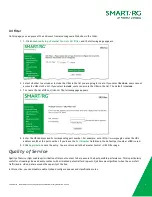
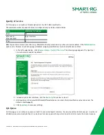
Page 71: ...age appears 4 Enter the URL address and its corresponding port number For example enter http www google com as the URL address and 80 as the port number If you leave the Port Number field blank the default port number of 80 is used 5 Click Apply Save to save the entry You are returned to the Parental Control URL Filter page Quality of Service Quality of Service QoS enables prioritization of Intern...

Page 72: ...ing classifications to wireless traffic has no effect 1 In the left navigation bar click Advanced Setup Quality Of Service The following page appears The Quality of Service feature is enabled by default 2 To disable QoS for ALL interfaces click the Enable QoS check box to clear it 3 Optional Select the default DSCP Mark Differentiated Services Code Point classification value to be used The default...

Page 73: ...SmartRG Inc an ADTRAN Company Proprietary and Confidential All Right Reserved 2020 73 1 In the left navigation bar click Advanced Setup Quality Of Service QoS Queue Config The following page appears ...

Page 74: ...S queue for the interface that you select Options are Enable and Disable The default is Enable Interface Select the Layer 2 interface to be associated with the defined QoS queue e g eth0 or ptm01 Precedence Appears when atm eth or ptm interfaces are selected in the Interface fields Select the priority value to be associated with the defined QoS queue Options vary by interface and can include 1 SP ...

Page 75: ...lows shaping of rate and burst size for packets in queue l Weighted Round Robin Applies a fair round robin scheme weighting that is effective for networks with fixed packet sizes e g ATM networks l Weighted Fair Queuing Applies a fair queuing weighting scheme via allowing different sessions to have different service shares for improved data packets flow in networks with variable packet size e g PT...

Page 76: ...fication On this page you can create classifications traffic class rules for assigning ingress traffic to a priority queue 1 In the left navigation bar click Advanced Setup Quality Of Service QoS Classification and then click Add The following page appears A maximum of 32 entries can be configured ...

Page 77: ...ptive name for this rule Rule Order This option is set to Last and cannot be changed Every rule is set as the very last classification rule to be processed Rule Status Select whether this rule is active or inactive Options are Enable and Disable The default is Enable Specify Classification Criteria section All fields in this section are optional A blank field identifies a criterion that is not use...

Page 78: ...otocol Options include default and a range of protocol IDs Protocol Available for WAN Local and ATM interfaces only Select the protocol specified for this classification Options are TCP UDP ICMP and IGMP UDP TCP Source Port Appears when TCP or UDP is selected in the Protocol field Enter the source port to be used for this classification You can enter a range port port or a single port UDP TCP Dest...

Page 79: ...he table enter a rate value for each column The default settings work for most scenarios 3 Click Apply Save to commit your changes Routing In this section you can configure default gateway static routing policy routing and RIP settings Default Gateway On this page you can select the WAN interface for the default gateway ...

Page 80: ...om left to right or right to left 3 Optional In the Selected WAN Interface field select the appropriate interface 4 Click Apply Save to implement the settings Static Route On this page you can configure static routes for your network Static route is a form of manually configured fixed route for IP data You can enter a maximum of 32 entries 1 In the left navigation bar click Advanced Setup Routing ...

Page 81: ...e WAN Interface for this route This list is filtered by the selected IP version Gateway IP Address Enter the next hop IP address If needed include the prefix length Metric Optional Enter a number that is zero or higher Policy Routing Policy routing makes somewhat automated routing choices based on policies defined by a network administrator For example a network administrator might want to deviate...

Page 82: ... are not allowed Physical LAN Port Select a physical LAN interface for the policy route Options include Ethernet LAN ports 1 4 and both wireless bands Source IP Enter the IP address for the source of the policy route Use Interface Select the WAN Interface for this policy route If you select an IPoE interface you must enter the IP address in the Default Gateway IP field Default Gateway IP Enter the...

Page 83: ... fields on this page are defined below Field Name Description Interface Displays a list of available WAN interfaces Version Select the applicable version of the Routing Interface Protocol For detailed information about versions refer to RFC 1058 and RFC 1453 Options are 1 2 and Both Operation This option is set to Passive and cannot be changed This mode listens only It does not advertise routes DN...

Page 84: ...faces Select interface entries in the lists and click the arrows to move the entries right or left l Define a static DNS IP address Click Use the following Static DNS IP address and enter the DNS server IP addresses l Obtain IPv6 DNS information from a WAN interface Select the interface in the WAN Interface Selected field If no WAN interface is configured this field is disabled l Define a static I...

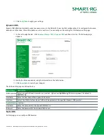
Page 85: ...The following page appears 2 Modify the fields as needed using the information in the table below 3 Click Apply Save to commit your changes The fields on this page are defined below Field Name Description D DNS provider Select a dynamic Domain Name Server provider Options are DynDNS org TZO or no ip com The default is DynDNS org Hostname Enter the host name of the dynamic DNS server Interface Sele...

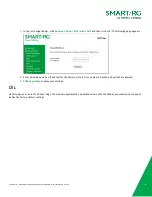
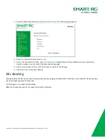
Page 86: ...d then click Add The following page appears 2 Enter a domain name and IP address for the domain Only letters numbers dashes and periods are allowed 3 Click Apply Save to apply your settings DSL On this page you can set the DSL settings The modem negotiates the modulation mode with the DSLAM you usually do not need to modify the factory default settings ...

Page 87: ...SmartRG Inc an ADTRAN Company Proprietary and Confidential All Right Reserved 2020 87 1 In the left navigation menu select Advanced Setup DSL The following page appears 2 Modify the settings as needed ...

Page 88: ...ngs arbitrarily is not recommended Close the window to return to the DSL Advanced Settings page 6 Click Apply and then click DSL in the left menu to return to the DSL page 7 Click Apply Save to save your changes DSL Bonding Bonding enables two DSL lines to feed the same modem and leveraging the bandwidth of both lines Once bonded the lines behave as a single higher bandwidth connection On this pag...

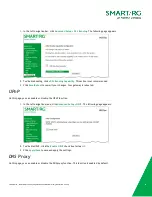
Page 89: ... recommended 3 Click Save Reboot to commit your changes Your gateway is rebooted UPnP On this page you can enable or disable the UPnP function 1 In the left navigation menu click Advanced Setup UPnP The following page appears 2 To disable UPnP click the Enable UPnP check box to clear it 3 Click Apply Save to save and apply the settings DNS Proxy On this page you can enable or disable the DNS proxy...

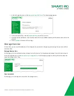
Page 90: ...ck Apply Save to implement the settings Storage Service In this section you can view information about the storage devices connected to the gateway and manage the user accounts that can access them Storage Device Info On this page you can view information about storage devices that connect to the gateway and manage the related user accounts In the left navigation menu click Advanced Setup Storage ...

Page 91: ...ome directory should be created d Click Apply Save to save your settings You are returned to the User Accounts page 3 To remove a user account click the Remove checkbox next to the account entry and then click the Remove button The list refreshes to show your changes were applied Interface Grouping On this page you can configure interface groupings Interface grouping supports multiple ports to PVC...

Page 92: ...SmartRG Inc an ADTRAN Company Proprietary and Confidential All Right Reserved 2020 92 1 In the left navigation menu click Advanced Setup Interface Grouping The following page appears ...

Page 93: ... appears 3 Follow the on screen instructions and then click Apply Save 4 To remove a grouping from the list click the Remove checkbox next to the group name and then click the Remove button You can only remove groupings that you create IP Tunnel IP Tunneling is typically used as a means to establish a path between two independent networks ...

Page 94: ...nd LAN interfaces associated with the tunnel you wish to establish 4 Do one of the following l To configure the LAN interface settings manually enter values in the fields located below the Manual button l IPv4 Mask Length Options are 0 32 l 6rd Prefix with Prefix Length Prefix length such as 2002 64 l Border Relay IPv4 Address IP address for the IPv4 relay server l To configure these settings auto...

Page 95: ...field do either of the following l To configure manually enter the remote address in the AFTR field l To configure automatically click Automatic above the AFTR field 5 Click Apply Save to commit your changes IPSec Internet Protocol Security is a protocol for securing communications by packet level encryption and authentication On this page you can enable and remove connections or edit existing con...

Page 96: ...3 Fill in the fields using the information in the field description table below Field Name Description IPSec Connection Name Enter a descriptive name for this connection NAT Transveral Click to enable the NAT traversal protocol IP Version Select the IP version for this connection Options are IPv4 and IPv6 The default is IPv4 ...

Page 97: ...ingle host Enter the IP address for the host IP Address Enter the IP address for local access Mask or Prefix Length Enter the subnet mask or prefix length for IP address entered for local access e g 255 255 255 0 Local ID Type Select the type of ID for the local VPN Options are Default Domain and E Mail The default is Default When you select Domain or E Mail the ID Content field becomes available ...

Page 98: ...orward Secrecy Select whether a session key derived from a set of long term keys is compromised if one of the long term keys in the set is compromised Options are l Enable Prevents long term keys from being compromised l Disable Permits long term keys to be compromised This is the default The following fields appear below Advanced IKE Settings when Manual is selected in the Key Exchange Method fie...

Page 99: ...ntegrity Algorithm Select the integrity algorithm Options are MD5 and SHA1 Select Diffie Hellman Group for Key Exchange Select the encryption group for exchanging keys Options range from 768 bit 8192 bit The default is 1024 bit Key Life Time Enter how long the key is effective in seconds The default is 3600 60 minutes 5 Click Apply Save to commit your changes Certificate In this section you can co...

Page 100: ...hority for signature The fields on this page are defined below Field Name Description Certificate Name Enter a certificate name A free form text field used to describe the intended use of the certificate Common Name Enter the IP address in dotted decimal notation domain name or email address Browsers use this information to verify your certificate is valid Organization Name Enter the name or the c...

Page 101: ...he left navigation bar click Advanced Setup Certificate Local Then click Import Certificate The following page appears 2 In the Certificate Name field type cpecert 3 Paste the Certificate details between the BEGIN and END markers 4 Paste the Private Key information between the BEGIN and END markers 5 Click Apply to commit this certificate ...

Page 102: ...pears 2 To import a certificate click Import Certificate The following page appears 3 In the Certificate Name field type a descriptive name for this certificate If you are using this certificate with TR 069 the name must be acscert 4 Paste the certificate details between the BEGIN and END markers 5 Click Apply to commit this certificate After you add one certificate a Remove button appears on the ...

Page 103: ...e is not currently supported Multicast On this page you can configure the multicast parameters 1 In the left navigation menu click Advanced Setup Multicast The following page appears 2 Fill in the fields using the information in the table below The fields provided for the IGMP and MLD configurations are largely the same ...

Page 104: ...tissa Query Response Interval Upon receiving a query packet a host begins counting down seconds from a random number When the timer expires the host sends its report Enter the maximum number of seconds that a host can pick to count down from The value must be greater than the Query Interval Last Member Query Interval Applies to MLD configuration only Enter the maximum response time within which th...

Page 105: ...r MLD Group Exception List tables The first two entries are created by default you cannot change these entries To add an exception type the IP address in the Group Address field enter the mask information in the Mask Mask bits field and then click Add To remove an exception click the Remove check box next to it and then click the Remove Checked Entries button Click Apply Save to implement your cha...

Page 106: ...s bridging Basic On this page you can configure basic features of the WiFi LAN interface You can enable or disable the WiFi LAN interface hide the network from active scans set the WiFi network name also known as SSID and restrict the channel set based on country requirements 1 In the left navigation bar click Wireless The following page appears 2 If you want to view or configure the 2 4GHz band s...

Page 107: ...ptional Enter the WiFi SSID For security purposes this identifier should be unique for your system BSSID Displays the Basic Service Set Identifier BSSID the MAC address assigned to the wireless router Country Select the country where this gateway will operate The wireless channel adjusts to the frequency provision for the selected country Country RegRev Enter the revision number of the country reg...

Page 108: ...ar access point wireless gateway to initiate the registration between a new device and an active access point wireless gateway The PBC method may also need a Registrar when used in a special case where the PIN is all zeros Seven types of network authentication modes are supported Open Shared 802 1X WPA2 WPA2 PSK Mixed WPA2 WPA and Mixed WPA2 WPA PSK 1 In the left navigation bar click Wireless Secu...

Page 109: ...security is assigned to clients l Configured The gateway assigns security settings to clients This is the default l Unconfigured An external client assigns security settings to the gateway Device PIN This value is generated by the access point 3 In the Manual Setup AP section select the SSID for the device that you want to configure The default is the wireless band defined for your gateway 4 Selec...

Page 110: ...th of the encryption method Options are 128 bit and 64 bit 128 bit is the default and is the more robust option for security Current Network Key Appears when WEP Encryption is set to Enabled Select which of the four keys is presently in effect Network Key 1 4 Appear when WEP Encryption is set to Enabled Enter up to four encryption keys using the on screen instructions to achieve the desired securi...

Page 111: ...ervers may use port 1645 Options are 1 65535 RADIUS Key Optional Enter the encryption key if needed to authenticate to the specified RADIUS server Encryption Strength Select the length of the encryption method Options are 128 bit and 64 bit 128 bit is the default and is the more robust option for security Current Network Key Select which of the four keys is presently in effect The default is 2 Net...

Page 112: ...ions are 0 65535 seconds The default is 0 RADIUS Server IP address Enter the IP address of the RADIUS Remote Authentication Dial In User Service server associated with your network RADIUS Port Enter the port number for the RADIUS server Options are 1 65535 Port 1812 is the default and is the current standard for RADIUS authentication per the IETF RFC 2865 Older servers may use port 1645 RADIUS Key...

Page 113: ...When you click Click here to display the passphrase appears in a separate window WPA Group Rekey Interval Enter the frequency at which the gateway automatically updates the group key and sends it to connected LAN client devices Options are 1 65535 seconds WPA Encryption Select the encryption standard This field is displays the option most compatible with the selected network authentication method ...

Page 114: ...te For this option to work you must add at least one MAC address to this page l Deny Reject requests from the wireless clients in the MAC Address list to access the wireless network 4 To add a MAC Address to the filter list a Click Add The following page appears b Enter the MAC address of the wireless client c Click Apply Save to save the address to the list You are returned to the Wireless MAC Fi...

Page 115: ...Address table to access the wireless LAN This is the default l Enabled Scan Allow only those bridges selected in the Remote Bridges MAC Address table to access the wireless LAN but the scanning feature is active l Disabled Disable the wireless MAC address filtering function Any wireless bridge can access the wireless LAN Remote Bridges MAC Address Enter up to four MAC addresses for the remote brid...

Page 116: ...ettings work for most environments It is recommended that only experienced users change settings on this page 1 In the left navigation bar click Wireless Advanced The following page appears 2 Modify the fields as needed using the information in the following table 3 Click Apply Save to commit your changes ...

Page 117: ...ghput With this option RTS CTS behavior permits legacy clients to become aware of 802 11n transmit times but decreases overall throughput This is the default l Off Provides better throughput Support MIMO Clients Only Select whether to restrict non MIMO clients from accessing the gateway Options are On and Off The default is Off RIFS Advertisement RIFS Reduced InterFrame Speed is the time in micro ...

Page 118: ...nter inconsistent data flow In that case make small reductions to this value until the issue is resolved DTIM Interval Enter the Delivery Traffic Indication Message DTIM or Beacon rate countdown variable used to indicate when the next window is available to client devices for listening to buffered broadcast and multicast messages Options are 1 255 The default is 1 Beacon Interval Beacon informatio...

Page 119: ...tic power saving feature Enabling ensures very low power consumption WMM Power Save is an improvement to the 802 11e amendment adding advanced power management functionality to WMM Options are Enabled and Disabled The default is Enabled Beamforming Transmission BFR Select to concentrate the transmission signal at the gateway location This results in a better signal and potentially better throughpu...

Page 120: ...To update the data click Refresh Wifi Insight On this page you can configure the WiFi Insight system to view statistics and metrics 1 In the left navigation menu click Wireless Wifi Insight The following page appears You can also reach this page by clicking Wireless Wifi Insight Configure ...

Page 121: ...ple Interval section select the number of seconds for sampling to occur Options are 5 10 15 and 20 seconds The default is 5 seconds 3 In the Start Stop Data Collection section configure the data sample a Click Start collecting data every b Select the days of the week when the data should be collected ...

Page 122: ...m size is reached Options are Overwrite Older Data and Stop Datacollection The default is Overwrite Older Data 5 Optional In the Counters list clear any counter options that you do not need The default is to collect all counters 6 Click Submit to save the configuration Site Survey On this page you can view signal strength and other details for your wireless networks 1 In the left navigation menu c...

Page 123: ... select the bandwidth 5 Click Scan The page refreshes to show the requested information Channel Statistics On this page you can view signal strength channel capacity interference and other details for specific channels In the left navigation menu click Wireless Wifi Insight Channel Statistics The following page appears ...

Page 124: ...ntial All Right Reserved 2020 124 Metrics On this page you can view glitch counter chanim associated stations and packet queue statistics for your wireless networks In the left navigation menu click Wireless Wifi Insight Metrics The following page appears ...

Page 125: ...e connection to your local network the connection to your DSL service provider and the connection to your Internet service provider 1 In the left navigation bar click Diagnostics The following page appears showing information about the connection encountered by the gateway 2 To run a test and refresh the data click the appropriate Test button The table is updated with fresh diagnostic information ...

Page 126: ...mpliant with IEEE 802 1ag for Connectivity Fault Management 1 In the left navigation bar click Diagnostics Ethernet OAM The following page appears 2 To enable Ethernet Link OAM 802 3ah a Click the Enabled checkbox Additional fields appear b Modify the fields as needed using the information in the Ethernet Link OAM 802 3ah section of the table below 3 To enable Ethernet Service OAM 802 1ag Y 1731 a...

Page 127: ...e test enter a MAC address in the Target MAC field and click Send Linktrace at the bottom of the page The results appear in the Linktrace Resultt row of the table The fields on this page are defined below Field Name Description Ethernet Link OAM 802 3ah section WAN Interface Select the WAN interface that you want to test OAM ID Enter the ID of this OAM configuration Only positive numbers are allow...

Page 128: ... maintenance entity group MEG ID Appears for the Y 1731 option only Enter the ID of the MEG Local MEP ID Enter the ID of the local maintenance entity group end point Options are 1 8191 The default is 1 Local MEP VLAN ID Enter the VLAN ID of the local MEP Options are 1 4094 The default is 1 no VLAN tag CCM Transmission Click to enable continuity check message transmission Remote MEP ID Enter the ID...

Page 129: ...e details of the ping appear on the page 4 To return to the Ping Host page click Back Trace Route to Host On this page you can use the traceroute utility to trace a connection 1 In the left navigation menu click Diagnostics Trace Route to Host The following page appears 2 Enter the host name or IP address ...

Page 130: ...SmartRG Inc an ADTRAN Company Proprietary and Confidential All Right Reserved 2020 130 3 Click Submit The details of the trace appear on the page 4 To return to the Trace Rout to Host page click Back ...

Page 131: ...current settings for your gateway in a file stored on your computer 1 In the left navigation bar click Management Settings The following page appears 2 To back up the current running settings a Click Backup Running Settings The Opening file dialog box appears b Click OK The file is saved to your default download location and is named backupsettings conf 3 To back up the current default settings a ...

Page 132: ...etting file or the default setting file conf file on your local system and click Open b Click Update Settings The gateway reboots when the update has completed Restore Default On this page you can restore the gateway to the factory default settings If you think you might need to reload the current settings create a backup on the Management Settings Backup page before proceeding 1 In the left navig...

Page 133: ... of error conditions and other events encountered by your gateway You can configure the system log and view the security log 1 In the left navigation bar click Management System Log The following page appears 2 To view the system log details a Click View System Log The log appears in a separate window b To update the data click Refresh ...

Page 134: ...ed to most detailed The default is Debugging Display Level Select the level of information that should be displayed Options are Emergency Alert Critical Error Notice Warning Informational and Debugging The options are listed in order from least detailed to most detailed The default is Error This level is recommended least verbose unless you are actively troubleshooting a situation with a subscribe...

Page 135: ...thorized resource access l Software update 1 In the left navigation bar click Management Security Log The following page appears 2 Do any of the following l To view the log click View The log appears in a separate window l To purge the log entries and start fresh click Reset A confirmation message appears Click Close l To export the log to a local drive right click the here link in the last line o...

Page 136: ...in the table below 3 Click Save Apply to commit your changes The fields on this page are defined below Field Name Description SNMP Agent This option is disabled by default Click Enable to enable the SNMP agent Read Community Select whether access to the network community is restricted Options are public and private The default is public Set Community Select whether access to the write set communit...

Page 137: ...ontains default connection parameters and generally only needs to be enabled pointed to the ACS URL and any required ACS Username and ACS Password entered This manual does not cover the setup of your ACS If you need to modify the default settings consult the materials provided by your ACS vendor to determine the appropriate parameters and server settings SmartRG products can accommodate several AC...

Page 138: ...your ACS platform requires it e g http customer1 acs smartrg com 30005 where 30005 is the port number The default port is 30005 ACS User Name Enter the user name by which this gateway logs in to the ACS ACS Password Enter the password to authenticate the above user name TR 069 Client Port Enter the TR 069 port number The default is 30005 WAN Interface used by TR 069 client Select any_WAN LAN Loopb...

Page 139: ... private network behind an ONT In this instance the regular CWMP Connection Request mechanism to talk to the modem gateway cannot be used to initiate a session with that ACS A STUN server receives STUN requests and sends STUN responses STUN servers are generally attached to the public Internet On this page when a STUN server is present within the infrastructure of the Service Provider you can conf...

Page 140: ...e maximum time in seconds that the keepalive function should be active Options are 0 Unlimited The default is 1 no maximum limit STUN Server Minimum Keep Alive Period Enter the minimum time in seconds that the keepalive function should be active Options are 0 Unlimited The default is 0 seconds This mechanism is used for refreshing NAT bindings with using Restricted Cone NAT or Port Restricted Cone...

Page 141: ... appear 3 Select the desired time servers 4 Select the Time zone offset 5 Click Apply Save to save and apply the settings 6 To disable this feature click the Automatically synchronize with Internet time servers check box to clear it and then click Apply Save to save your changes Access Control In this section you can manage user passwords and the services that are available for users The following...

Page 142: ...that your gateway can access 1 In the left navigation bar click Management Access Control The following page appears You can also access this page by clicking Management Access Control Services 2 Select or clear the enable checkbox next to each service and interface that you want to change 3 Optional For the HTTP S service select whether to use encrypted HTTP S Note When you select this option the...

Page 143: ...in accounts for its on board user interface Each account can be customized to grant access privileges to specific pages in the interface This is particularly useful when an ISP wants to limit access for subscribers yet grant full access for technical support and on site installation personnel Add an Account 1 In the left navigation bar click Management Access Control Accounts The following page ap...

Page 144: ...ppears 3 Enter a Username and Password for the new account 4 Select the features that you want this user to access If you select a subcategory the subordinate boxes are also selected 5 Click Save Account to commit your changes The new account is created To test the account credentials log out of the interface and then log back in using the new account ...

Page 145: ...it Account page appears 2 In the Select an account field select the account you wish to modify or delete 3 Do one of the following a To modify an account check or clear the desired boxes and then click Update Account to commit your changes b To disable or enable an account click the applicable Enable Disable account button and then click Update Account c To delete an account scroll to the bottom o...

Page 146: ...current password in the Old Password field 4 Enter the new password in the New Password and Confirm Password fields Passwords cannot contain spaces 5 Click Apply Save to implement your changes Access List On this page you can create list of IP addresses that are allowed to access local management services defined in the Services Control list When Access Control mode is disabled IP addresses for in...

Page 147: ...lowing page appears 2 Click Add The following page appears 3 In the Source Address field enter the IP address and mask of the station allowed to access local management services 4 Click Apply Save You are returned to the Access Control IP Address page Logout Timer On this page you can define the maximum time that a session can remain open before the gateway logs out ...

Page 148: ...ftware On this page you can update the firmware of your gateway Software updates for SmartRG product are available for download by direct customers of SmartRG via the SmartRG Customer Portal Note Make sure that you have downloaded the correct software file as instructed by your ISP 1 In the left navigation bar click Management Update Software The following screen appears 2 Click Browse to locate a...

Page 149: ...eserved 2020 149 Reboot On this page you can reboot your gateway without needing physical access to the unit 1 In the left navigation click Management Reboot The following page appears 2 Click Reboot The gateway reboots and after a few minutes the Login dialog box appears ...

Page 150: ...AN Company Proprietary and Confidential All Right Reserved 2020 150 Logout 1 To log out of your gateway click Logout in the left navigation menu The Logout page appears 2 Click the Logout button A success message appears ...

Page 151: ... of the following measures l Reorient or relocate the receiving antenna l Increase the separation between the equipment and receiver l Connect the equipment into an outlet on a circuit different from that to which the receiver is connected l Consult the dealer or an experienced radio TV technician for help This Class B digital apparatus complies with Canadian ICES 003 Cet appareil numrique de la c...

Page 152: ... advance notice in order for you to make necessary modifications to maintain uninterrupted service If trouble is experienced with this equipment for repair or warranty information please contact SmartRG Inc If the equipment is causing harm to the telephone network the telephone company may request that you disconnect the equipment until the problem is resolved Connection to party line service is s...

Page 153: ... 20 centimeters between the radiator and your body Cet émetteur ne doit pas être Co placé ou ne fonctionnant en même temps qu aucune autre antenne ou émetteur Cet équipement devrait être installé et actionné avec une distance minimum de 20 centimètres entre le radiateur et votre corps This radio transmitter identify the device by certification number or model number if Category II has been approve...

Page 154: ...are release 2 6 2 4 1 5 September 2019 Updated information to match firmware release 2 6 2 3 1 4 July 2019 Updated information to match firmware release 2 6 2 2 1 3 July 2017 Updated to match release 1 0 0 76 1 2 May 2017 Corrected wireless radio button instructions 1 1 March 2017 Multiple updates to match current environment 1 0 August 2016 Initial release of this user manual ...

Reviews: