Total Access
®
3000/3010 System Manual
6TADLP705-1E
TOTAL ACCESS 3000/3010
DLP-705
Page 2 of 4
© 2002, ADTRAN, Inc.
Perform Steps Below in the Order Listed
1.2
Detailed Level Procedure 705
1.2.1
To Access the Digital Loop Testing Facilities on Total Access 3000/
3010:
1.Locate Digital Loop Wiring
After you have located the test loops and run them to the Total Access 3000/3010
shelf, use wire strippers to strip approximately 1 inch to 1-1/2 inches from the test
leads.
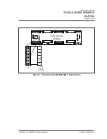
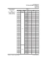
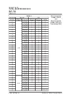
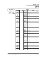
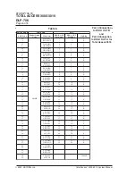
2.Connect the “T” and “R” Leads (see Figure 1)
Using the wire-wrap tool, wire wrap the central office “T” and “R” leads to the
Total Access 3000/3010 “T” and “R” pins, respectively, on terminal P23/P22.
3.Terminate the Sheild Drain Wire
Wire wrap the drain wire of the cable to the top pin labeled “S” on P23/P22. The
shield drain wire should be grounded at either the test head or the Total Access
3000/3010 shelf, but not both. If the drain wire is grounded at the test head, Step
1.3 should not be done. Instead, trim the drain wire off at the insulation.
4.Connect the “T1” and “R1” Leads
Wire wrap the central office “T1” and “R1” leads to the Total Access 3000/3010
“T1” and “R1” pins, respectively, on terminal P23/P22.
5.Terminate the Sheild Drain Wire
Wire wrap the drain wire of the cable to the bottom pin labeled “S” on P23/P22.
The shield drain wire should be grounded at either the test head or the Total
Access 3000/3010 shelf, but not both. If the drain wire has been terminated from
Step 3 above, do not also terminate the drain wire to the test head. Instead, trim
the drain wire off at the insulation.
6.Dress Out the Wiring
Neatly tie down the test cable pair.
1.3
Followup Procedures
Once this procedure is complete, return to the procedure which called out this DLP and
continue with the tasks indicated there.


