Total Access
®
3000/3010 System Manual
6TADLP707-1E
TOTAL ACCESS 3000/3010
DLP-707
Page 2 of 4
© 2002, ADTRAN, Inc.
Perform Steps Below in the Order Listed
1.2
Detail Level Procedure 707
1.
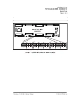
Remove the plastic protector from the backplane connector to be wired.
2.
Noting the orientation of the backplane male connection receptacle, push the
female cable connector onto the backplane connector.
3.
Using a small straight-slot screwdriver, snug the screw on the right side
of the cable connector into the hole provided on the backplane connector.
Secure the connector into place on the left side by tightening the wire tie
around the body of the cable connector.
4.
Using a side cutter, snip the wire tie end off flush with the barrel of the tie.
5.
Repeat Steps 1-4 for each connector on the backplane being used for your
application.
NOTE
All data cables should exit the Total Access 3000/3010 shelf to the left (as
viewed from the rear), and be neatly tied to the frame as per CO SOP. All other
wiring, for example power, loop test access, clock, external alarms, should
exit to the right and be tied off on the right side of the frame. The ground wire,
attached to J33/J22 on the backplane, should be routed to the nearest suitable
grounding point.
6.
Neatly tie off the data cables to the left of the shelf.
7.
Route the cables through the cable trays to the terminal blocks on the
horizontal side of the MDF.
CAUTION
Electronic modules can be damaged by static electrical discharge. Before
handling modules, wear an antistatic discharge wrist strap to prevent damage
to electronic components. Place modules in antistatic packing material when
transporting or storing. When working on modules, always place them on an
approved antistatic mat that is electrically grounded.


