Total Access
®
3000/3010 System Manual
6TADLP702-1E
TOTAL ACCESS 3000/3010
DLP-702
Page 1 of 4
© 2002, ADTRAN, Inc.
Perform Steps Below in the Order Listed
1.1
Connecting a Composite Clock Input to a Shelf
NOTE
References to common, but differing, parameters between the Total Access
3000 and the Total Access 3010, such as number of slots, will be conveyed
by the convention a/b. The “a” represents the Total Access 3000 parameter
and the “b” represents the Total Access 3010 parameter. For example, the
differing number of access slots in the two platforms, 28 for the Total Access
3000 and 22 for the Total Access 3010, would be displayed “28/22.”
1.1.2
Introduction
The Total Access 3000/3010 terminates an external composite clock source for
applications requiring composite clock timing. This procedure assumes that an
appropriate drop wire (shielded two-wire with drain) from the CO clock source has
been run to the Total Access 3000/3010 shelf and is ready for connection. A detailed
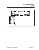
illustration (
) of the Total Access 3000/3010 Clock Connections may be
found on page 4 of this DLP. See PREP-401, Section 3, of this system manual for a
further description of the clock source wire.
1.1.3
Prerequisite Procedures
Remove the large Plexiglass guard from the Total Access 3000/3010 backplane if it is
not already removed from a preceding Installation and Turn up procedure. See
DLP-701 for details about removing the guard.
1.1.4
Tools and Materials Required
• Wire strippers
• Wire-wrap tool
WARNING
To prevent electrical shock, do not install equipment in a wet location or
during a lightning storm.
CAUTION
Electronic modules can be damaged by static electrical discharge. Before
handling modules, wear an antistatic discharge wrist strap to prevent damage
to electronic components. Place modules in antistatic packing material when
transporting or storing. When working on modules, always place them on an
approved antistatic mat that is electrically grounded.


