


4
61287737F3-13A
Step 5: Connect Power
Plug the supplied 12 V AC/DC Power Converter into the
PWR
connection on the rear of the ONT. Connect the power plug to a
standard 120 VAC outlet.
Using a UPS
The ONT can typically use an Uninterruptible Power Supply
(UPS) if desired. Power is supplied to the ONT by a local power
source with battery backup that uses the AC power at the
customer premises to maintain the charge on the battery. The
UPS powers the ONT and functions as a battery back-up unit
(BBU) supplying continuous 12 VDC. For installation instructions,
refer to the installation material provided with the UPS.
If a UPS is disconnected while in use, the ONT is not protected
from power outages and will send a “Battery Missing” alarm to the
OLT.
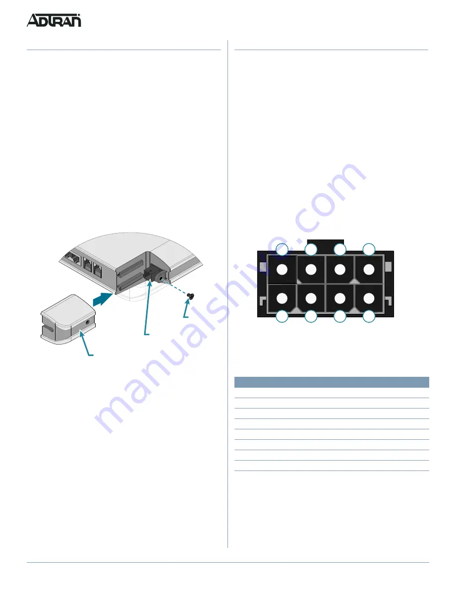
Connecting a UPS
Connect the UPS to the 8-pin MOLEX connector labeled “UPS”
located on the rear of the SFU ONT chassis.
represents
the MOLEX connector.
Figure 4. UPS Connector
The UPS Power/Alarm Connections Table below provides a pin-
out for the connector.
ADTRAN offers a UPS Cable assembly (P/N: 1287402G1) for this
connector.
ON/OFF Button
An
ON/OFF
button is located on the far-left side of the rear of the
ONT. User functionality is limited to this button.
Pin-Out
Description
Alarm
1
Power Input (+12 VDC)
-
2
UPS Status - On Battery
1
3
UPS Status - Battery Missing
2
4
Signal Return
-
5
Power 12 V Return
-
6
UPS Status - Replace Battery
3
7
UPS Status - Low Battery
4
8
No Connection
-
8
7
6
5
4
3
2
1
Step 4: Install Fiber
C
CAUTION!
■
LASER RADIATION
■
1310 nm to 1490 nm
■
Do not view directly with optical instruments.
■
This product contains a Class 1 Laser module that complies
with FDA 21 CFR 1040.10, 1040.11 and IEC 60825-1.
Fiber is installed in an SC connecter located behind a removable
protector panel (labeled “Fiber Port”) on the right-rear of the ONT.
Refer to
.
g
NOTE
does not apply to all installations. Some ONT units have
a screw; others have a protective cover that simply slides off in
the direction of the arrow on the cover.
1. If equipped, remove the Phillips-head screw from the right
side of the fiber protector panel.
Slide the protector cover back to expose the SC connector.
Figure 3. Fiber Installation
2. Clean the ends of the incoming fiber at the SC connection.
3. Before installing the fiber, use an optical power meter to
measure the optical power. The level should not exceed –8
dBm. Use an appropriate bi-directional optical attenuator if
the power levels are at or above –8 dBm. A level between
–12 and –27 dBm is acceptable.
4. Connect the incoming fiber cable to the SC connection.
5. Route the fiber cable through the slot in the protective cover
and slide it back into place.
6. Replace and secure the panel (use the Phillips screw if
equipped).
Protective Cover
SC Connector
Screw


