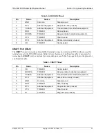
TRACER 6000 Series Split System Manual
Section 3 Engineering Guidelines
612806320L1-1B
Copyright © 2005 ADTRAN, Inc.
31
1.
EQUIPMENT DIMENSIONS
The TRACER 6200 Indoor Unit (IDU) is 17.2 inch (43.7 cm) W, 11.4 inch (28.9 cm) D, and 1.7 inch
(4.4 cm) H, weighs 5 pounds (2.3 kg), and can be used in rackmount configurations. The Outdoor Unit
(ODU) is 10.24 inch (26.01 cm) W, 4.78 inch (12.14 cm) D, and 12.74 inch (32.36 cm) H, weighs
9.5 pounds (4.3 kg), and can be mounted using standard U-bolts.
2.
POWER REQUIREMENTS
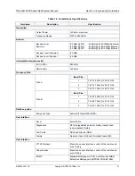
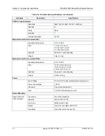
The TRACER 6000 Series system has a maximum power consumption of 25 W and a maximum current
draw of 1.8 A (at 21 VDC).
3.
REVIEWING THE FRONT PANEL DESIGN
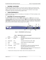
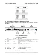
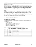
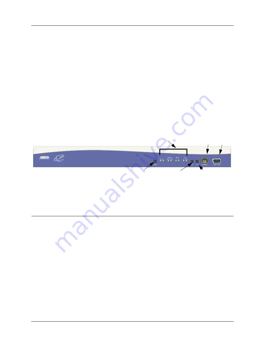
The TRACER 6200 front panel contains an
RSSI
monitoring interface, a
GND
interface for reference
with RSSI, a
TEST
interface for factory use only, a DB-9
CRAFT
port for management and configuration,
an
AUX RS232
interface (RJ-45) that provides an end-to-end serial port interface (at 9600 bps), and status
LEDs to provide visual information about the TRACER system. Figure 1 identifies the various interfaces
and the LEDs, and Table 1 provides a brief description of each interface.
Figure 1. TRACER 6200 Front Panel Layout
Table 1. TRACER 6200 Front Panel Description
1
1
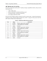
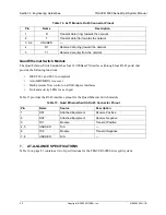
Detailed discussions (including pinouts) of front panel components (where applicable) follow the table.
Name
Connector
Description
A
RSSI
bantam
DC voltage indicating strength of the received signal at the
antenna
B
Status LEDs
N/A
Visual status information about the system
C
GND
bantam
Ground reference for the RSSI interface
D
Test
3.5 mm mini-jack
Factory use only
E
AUX RS232
RJ-45
Serial interface for a 9600 bps connection between the
local and remote systems over the RF link
F
CRAFT PORT
DB-9
RS-232 interface for connection to a VT100 terminal or PC
with terminal emulation software
TRACER 6200
B
C
A
E
F
D

