TRACER 6000 Series Split System Manual
Section 3 Engineering Guidelines
612806320L1-1B
Copyright © 2005 ADTRAN, Inc.
39
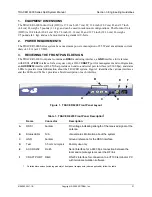
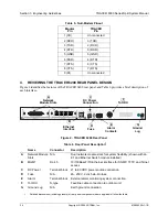
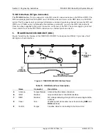
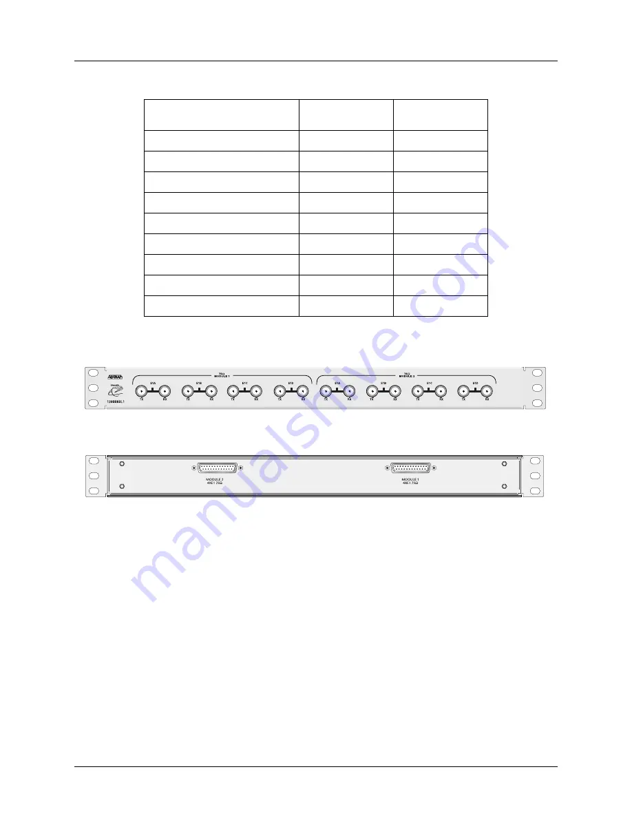
Figure 4. E1 Breakout Panel
4xT1 Module
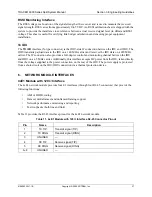
The 4xT1 network module has four T1 interfaces (through four RJ-45 ports) that provide the following
functions:
•
ANSI T1.403 and AT&T
®
54016 and 62411 compliant
•
AMI or B8ZS coding
•
Extended Super Frame (ESF) and Super Frame (SF) framing support
•
Manual line build out
•
Network performance monitoring and reporting
•
Test loopbacks (both line and link)
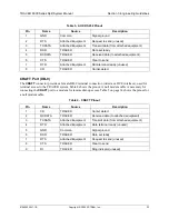
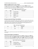
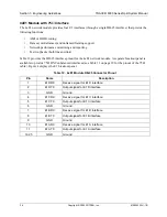
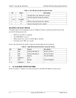
Table 14 on page 40 provides the RJ-45 interface pinout for the 4xT1 network module.
Table 13. DB-25 to 75
Ω
Unbalanced Cable Pinout
E1 Cable Interface
DB-25 Male
(TRACER Side)
DB-25 Male
(Breakout Panel)
Channel 1 Input
10
14
Channel 1 Output
11
3
Channel 2 Input
7
17
Channel 2 Output
8
6
Channel 3 Input
4
20
Channel 3 Output
5
9
Channel 4 Input
1
23
Channel 4 Output
2
12
Ground
All other pins
All other pins

