TRACER 6000 Series Split System Manual
Section 4 Network Turnup Procedure
612806320L1-1B
Copyright © 2005 ADTRAN, Inc.
53
Instructions for Installing Network Modules
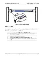
Individual access modules insert in the back of the chassis. Two phillips-head screws hold the modules in
place for added security. To install network modules, follow the steps outlined below.
9.
CONNECTING THE MODULE INTERFACES
Quad T1 Module Interfaces
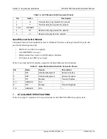
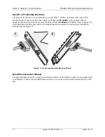
The physical T1 interfaces are provided using four RJ-45 ports located on the module. Straight-through T1
interface cables can be used to interface to any standard T1 DTE device (not supplied).
Quad E1 (120
Ω
) Module Interfaces
The physical E1 interfaces are provided using four RJ-45 ports located on the module. Straight-through E1
interface cables can be used to interface to any standard E1 DTE device (not supplied).
Electronic modules can be damaged by static electrical discharge. Before handling
modules, put on an antistatic discharge wrist strap to prevent damage to electronic
components. Place modules in antistatic packing material when transporting or storing.
When working on modules, always place them on an approved antistatic mat that is
electrically grounded.
Instructions for Installing Network Modules
1.
Remove power from the unit.
2.
Remove the blank panel plate (if necessary).
3.
Slide the network module into the network slot until the module is firmly seated
against the front of the chassis.
4.
Secure the screws at both edges of the module.
5.
Install the optional hardware components (when necessary). For example, for
the E1 network module, an optional BNC breakout panel is available.
6.
Connect the cables to the associated device(s).
7.
Restore power to the unit.
T1 crossover cables are needed when connecting two TRACER 6000 Series T1 ports in
back-to-back operation.
E1 crossover cables are needed when connecting two TRACER 6000 Series E1 ports in
back-to-back operation.


