Section 5 User Interface Guide
TRACER 6000 Series Split System Manual
64
612806320L1-1B
> RF L
INK
C
ONFIGURATION
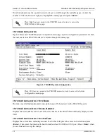
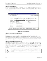
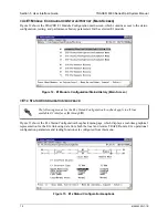
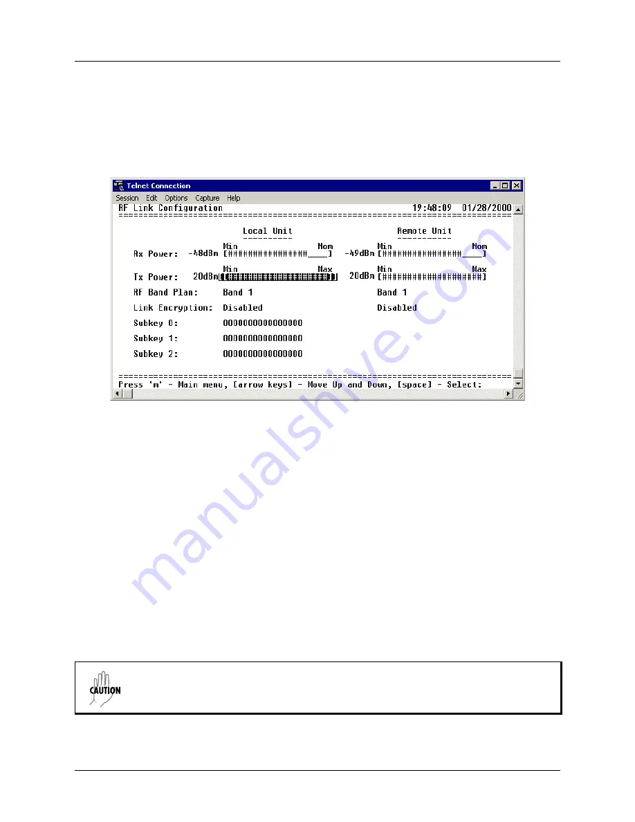
Figure 5 shows the TRACER RF Link Configuration menu page, which contains the transmit and receive
power settings and band plan configuration for both the local and remote units. Triple-DES encryption is
also configured from this menu.
Figure 5. RF Link Configuration
> RF L
INK
C
ONFIGURATION
> RX P
OWER
Displays the real-time receiver levels (for both the local and remote units) in dBm and a visual
approximation using a series of symbols (
#
). The more symbols (
#
) displayed, the stronger the signal.
Real-time receiver levels are displayed within ±5 dBm accuracy and can vary with extreme temperatures.
If the link is down in either direction and remote end data is unavailable,
D
ATA
N
OT
A
VAILABLE
displays in
place of the symbols (
#
). This parameter is display only.
> RF L
INK
C
ONFIGURATION
> TX P
OWER
Allows the transmitter levels (for both the local and remote units) to be adjusted. The current transmitter
level is displayed in dBm or a visual approximation using a series of symbols (
#
). The more symbols (
#
)
displayed, the stronger the signal. Real-time receiver levels are displayed withing ±1 dBm accuracy. If the
link is down and remote end data is unavailable,
D
ATA
N
OT
A
VAILABLE
displays in place of the symbols (
#
).
Pressing (
+
) on this field sets the
T
X
P
OWER
to full strength; pressing (
-
) reduces the
T
X
P
OWER
to the
minimum.
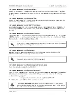
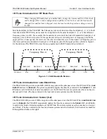
Reducing the transmitter power of the remote TRACER could cause the RF link to drop,
requiring a technician to increase the transmit power by using the menu system at the
remote site.


