Section 5 User Interface Guide
TRACER 6000 Series Split System Manual
66
612806320L1-1B
> RF L
INK
P
ERFORMANCE
H
ISTORY
(M
AIN
S
CREEN
)
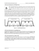
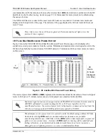
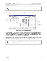
Figure 7 shows the TRACER RF Link Performance History main screen, which contains the transmit and
receive power settings and band plan configuration for both the local and remote units.
Figure 7. RF Link Performance History (Main Screen)
> RF L
INK
/ODU E
RROR
H
ISTORY
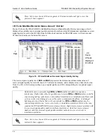
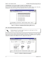
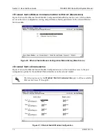
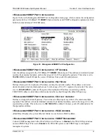
Figure 8 shows the TRACER RF Link/ODU Error History menu page, which displays the error statistics
available from the system for the RF link and the communications link between the IDU and ODU.
Detailed error statistics are displayed in 15-minute and 24-hour increments.
Figure 8. RF Link/ODU Error History
The (
ODU
) represents the number of seconds that the IDU was unable to communicate with the ODU over
the communications link. The number of seconds without IDU/ODU communication that occur in a
24-hour or 15-minute increment are displayed as a numerical value.
ODU
errors can indicate a problem
with the IF cabling between the IDU and ODU. Link errors (
LNK
) represent the number of seconds of lost
7
Days
24
Hours
(8 hours
displayed
at a time)


