Chapter 3. Operation
40
TSU 120 User Manual
61200.129L1-1
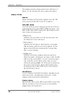
The display panels and operation keys called out in
Figure 3-1 are described in the sections that follow.
Display Panels
Remote
When illuminated, this panel indicates that the TSU
120 is accessed remotely by the PC program.
DSU/DSX Status
The TSU 120 basic unit is equipped with an Nx56/64
serial interface port and a DSX-1 (PBX) interface. The
DSU/DSX status LEDs display the operational condi-
tion of these two base ports.
• OK (green)
Indicates the operation is in the normal mode and
no alarms have been detected.
• Test (yellow)
Indicates the interface is operating in a test mode.
This includes a self test or a test loopback. When
lighted, this LED also indicates that normal data
flow is not occurring.
• Alarm (red)
Indicates an alarm condition has been detected.
When the alarm condition is no longer valid, the OK
LED activates (turns ON). To view an alarm condi-
tion, select the active alarm menu item or select
Alarm by pressing shift + 8. If the alarm conditions
have been corrected, the alarm which caused the
activation of the Alarm LED can be viewed under
the Unit History menu.
LCD Window
A 2x16 character backlit LCD window displays menu
items used in the configuration of the unit. It also
displays alarm and status information.
Module Status
Operates the same as the DSU status LEDs except they
indicate the status of the data ports on the module
plugged into the option slot.
Summary of Contents for TSU 120
Page 1: ...TSU 120 PART NUMBER 1200129L1 USER MANUAL 61200 129L1 1A July 1997...
Page 52: ...Chapter 2 Installation 38 TSU 120 User Manual 61200 129L1 1...
Page 132: ...Appendix C System Configuration Charts 118 TSU 120 User Manual 61200 129L1 1...
Page 138: ...Appendix D TSU 120 System Messages 124 TSU 120 User Manual 61200 129L1 1...


