


A - 10
ET600 - 100, 400 - 56091033
8/11
INSTRUCTIONS FOR USE
REVISED DATE
ENGLISH
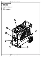
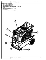
OPERATING THE MACHINE
1
Follow the instructions in the
Preparing the Machine for Use
section of this manual.
2
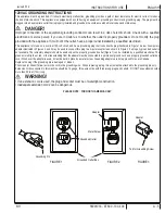
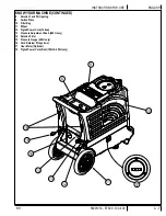
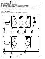
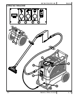
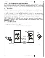
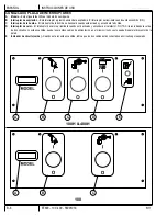
Turn off all the switches. Plug the power cords into properly grounded outlets. Do not connect both cords to the same outlet; the green,
Circuit Indicator Light
(E)
on the switch plate should light up. If the indicator light does not come on, try different outlets until it does. Do not
connect both cords to the same outlet.
3
Attach the priming hose to the machine and place the open end into the solution tank.
4
Turn ON the solution pump
(C)
and let it run until the pump is fully primed (approximately 30 seconds to 1 minute). Once the pump is primed,
turn off the pump and remove the priming hose.
NOTE:
If priming is dif
fi
cult, place the open end of the priming hose into the Vacuum inlet
hose barb, and turn the vacuum on. Use your hand to block the open area in the hose barb. This will allow the pump and the vacuum to work
together to get the water moving.
5
Connect a solution line to the Solution Hose Quick Disconnect
(5)
. Attach the other end of the solution line to the cleaning tool.
6
Connect a vacuum hose to the Vacuum Hose Barb
(2)
. Attach the other end of the vacuum hose to the cleaning tool.
7
To use heated water for cleaning, press the Heat Switch
(D)
on. Wait two minutes for the heat exchanger to reach temperature.
8
Press the Pump Switch
(C)
to ON (I).
9
Press the Vacuum Switch
(B)
to ON (I).
10
Spray through your tool a few times to
fi
ll the lines with solution. Begin cleaning.
11
Note for 400H models only:
To adjust the solution spray pressure; rotate the Pressure Adjustment Knob
(13)
clockwise to increase pressure
and counterclockwise to decrease pressure. The pump spraying pressure will be observable at the Pressure Gauge
(15)
while spraying. Make
sure the cleaning tool is spraying when adjusting the pressure, otherwise the pressure reading will be inaccurate.
12
Watch
the
fl
uid entering the Recovery Tank Lid
(1)
. If there is a large amount of suds in the recovery tank, add a defoamer chemical to the
recovery tank.
CAUTION!
• Empty the recovery tank before the
fl
uid or foam enters the vacuum motor.
• If foam or liquid escapes from the machine, switch off immediately.
CAUTION!
Always make sure the
fl
oat is clean and travels freely before turning on the machine. A
fl
oat that is stuck will cause the
vacuum motor to suck in water, resulting in vac motor damage.
13
The recovery tank has a Recovery Tank Shutoff Float
(7)
to block the vacuum system when the recovery tank is full. You can tell when the
fl
oat
closes by the sudden change in the sound of the vacuum motor. When the
fl
oat closes, the recovery tank must be emptied. The machine can
continue to dispense solution, but
will not
pick up water with the
fl
oat closed.
14
Monitor the water level in the solution tank. Do not let the pump run dry. When the solution tank gets low, turn off the pump and the vacuum
motor, re
fi
ll the solution tank with water and the proper ratio of cleaning detergent. Empty the recovery tank and continue cleaning.
15
When the operator has completed the job; vacuum all unused solution from the solution tank into the recovery tank, turn off the pump, vacuum
motor and heat exchanger. Unplug the machine.
16
Push the machine to a designated waste water “DISPOSAL SITE” and empty the recovery tank. Drain the recovery tank by opening the drain
gate
(3)
over a drain or a bucket.
17
Follow the instructions in the
After Using the Machine
section of this manual.