8
- FORM NO. 56043096 - Captor
™
4300B, 4800B
STEERING SYSTEM
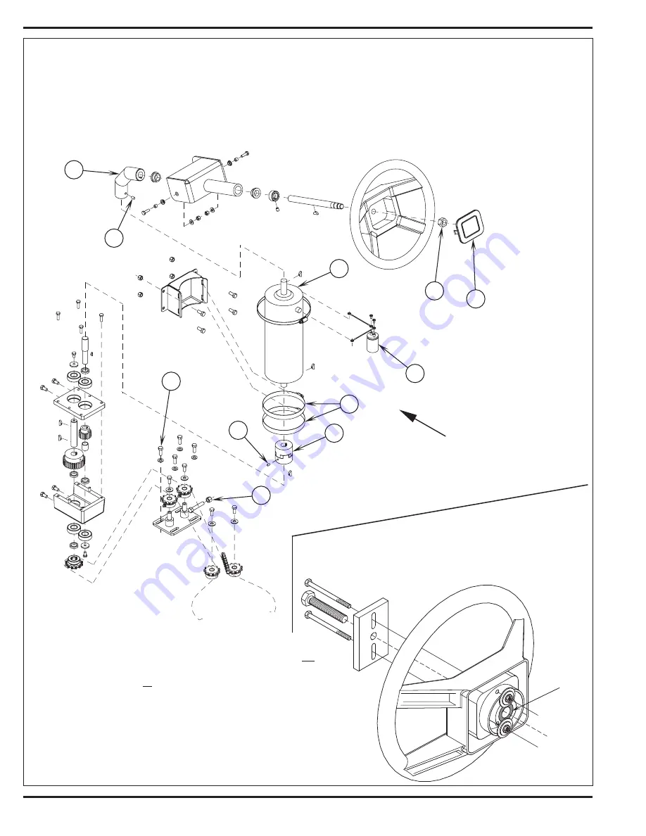
STEERING WHEEL REMOVAL
1
See Figure 1.1. Pry up steering wheel Cap
(A)
.
2
Remove center hex Nut
(B)
. Note: This is a metric nut, you will need a 24mm socket.
3
Use a steering wheel puller to remove steering wheel from splined shaft. Note: It may be necessary to enlarge holes in steering wheel, also be
sure to support the metal splined bushing in the center of the steering wheel (see Figure 1.2) when pulling the wheel.
POWER STEERING UNIT REMOVAL
1
Disconnect the battery by using the Emergency Disconnect Knob
(KK)
.
2
Remove the 4 screws that fasten the steering unit cover to the chassis.
3
Open the Battery Cover
(21)
to access the Universal Joint
(C)
and loosen its
lower Setscrew
(D)
.
4
Remove the wires to the Motor
(E)
and Capacitor
(F)
, note location of wires
for reinstallation (salvage capacitor).
5
Remove Setscrew
(G)
from lower Coupler
(H)
and pry up on coupler with a
flat screwdriver to separate.
6
Loosen the 2
(I)
Hose Clamps and remove motor.
7
Follow above steps in reverse order to reassemble.
FIGURE 1.2
FIGURE 1.1
Summary of Contents for 56303000
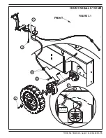
Page 17: ...FORM NO 56043096 Captor 4300B 4800B 15 FRONT WHEEL SYSTEM FIGURE 3 1...
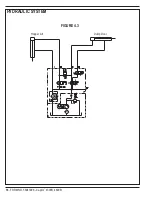
Page 20: ...18 FORM NO 56043096 Captor 4300B 4800B HYDRAULIC SYSTEM FIGURE 4 3...
Page 33: ...FORM NO 56043096 Captor 4300B 4800B 31 SOLUTION SYSTEM FIGURE 7 1...
Page 39: ...FORM NO 56043096 Captor 4300B 4800B 37 SQUEEGEE SYSTEM FIGURE 10 1...
Page 41: ...FORM NO 56043096 Captor 4300B 4800B 39 SQUEEGEE SYSTEM FIGURE 10 2...
Page 45: ...FORM NO 56043096 Captor 4300B 4800B 43 WIRING SCHEMATIC before SN 1767238 ELECTRICAL SYSTEM...
Page 50: ......


