14
- FORM NO. 56043096 - Captor
™
4300B, 4800B
FRONT WHEEL SYSTEM
FRONT WHEEL REMOVAL AND BRAKE INSPECTION
1
Raise hopper and engage safety support.
2
Open broom-housing door (LH or RT) and remove the top gasket seal (so not to damage). Place jack towards front of housing and jack on
machine frame to where the front wheel clears the floor.
3
Place safety blocking under the front frame member to support.
4
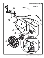
See Figure 3.1. Remove the Wheel Screw
(A)
then work the tire(s) off of wheel spindle. Note: the parking brake must be released to allow
wheel to be removed. Also tap on the backside of wheel with wood blocking to help loosen a stubborn stuck wheel.
5
Inspect the spindle; wheel bearings and brake shoe linings for abnormal wear and replace all worn parts. A new brake shoe lining thickness
will measure 11/64 (.172) inches or 4.4mm.
6
Check for approximately one inch (25mm) of operator brake pedal free-play (see instructions below to adjust) and test drive machine for proper
operation.
FRONT BRAKE SHOE ADJUSTMENT
1
See Figure 3.1 detail of Brake Cable mounting nuts. Note both cables need to be adjusted equally. From underneath the machine shorten or
lengthen the number of cable threads extending out of the cable casing by adjusting the cable anchor nuts to obtain the proper Brake Pedal
free play, approximately one inch (25mm). NOTE: Fewer threads will equal a tighter Brake Pedal.
BRAKE CABLE REPLACEMENT
1
See
Front Wheel Removal and Brake Inspection
instructions to access the Brake Cable clevis and anchor nuts.
2
See Figure 3.1. Remove the brake cable from the brake arm by removing Screw and Nut
(B & C)
and then loosen the cable Anchor Nuts
(D)
and pull brake cable casing from its mount. Repeat procedure for other wheel.
3
Loosen the cable anchor nuts (location middle of machine under operator floor plate) slide Cable anchor nuts out of their mounts.
4
Remove Screw
(E)
Nut
(F)
from the brake pedal cable guide pulley and remove pulley from the cable.
5
From underneath the machine guide the cable though the chassis to complete the removal of the cable assembly.
6
Install the new cable see Figure 3.1 for proper dimensions.
7
Tighten the cable anchor nuts at the front wheel then turn the ball joint on the new cable end until it lines up with the brake arm then reattach
the Screw and Nut
(B & C)
. Repeat procedure for other wheel.
8
Mount both wheels back on the machine.
9
From underneath the machine hand tighten Anchor Nuts
(D)
to the proper dimension.
10
Press the Brake Pedal a few times to take up any cable slack then check for proper free play approximately one inch (25mm) in the Brake Pedal
if too loose or tight see
Front Brake Shoe Adjustment
.
11
When Brake Pedal is adjusted properly, tighten the
(D)
Anchor Nuts.
Summary of Contents for 56303000
Page 17: ...FORM NO 56043096 Captor 4300B 4800B 15 FRONT WHEEL SYSTEM FIGURE 3 1...
Page 20: ...18 FORM NO 56043096 Captor 4300B 4800B HYDRAULIC SYSTEM FIGURE 4 3...
Page 33: ...FORM NO 56043096 Captor 4300B 4800B 31 SOLUTION SYSTEM FIGURE 7 1...
Page 39: ...FORM NO 56043096 Captor 4300B 4800B 37 SQUEEGEE SYSTEM FIGURE 10 1...
Page 41: ...FORM NO 56043096 Captor 4300B 4800B 39 SQUEEGEE SYSTEM FIGURE 10 2...
Page 45: ...FORM NO 56043096 Captor 4300B 4800B 43 WIRING SCHEMATIC before SN 1767238 ELECTRICAL SYSTEM...
Page 50: ......


