20
- FORM NO. 56043096 - Captor
™
4300B, 4800B
SWEEPING SYSTEM
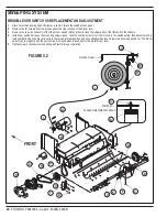
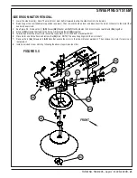
BROOM LEVER SWITCH S8 REPLACEMENT AND ADJUSTMENT
1
Drain, unlatch and swing open the recovery tank to locate the switch access panel.
2
Remove the (4) screws from the access panel near the location of the broom lever.
3
Remove the two wire connectors from the broom switch (S8) and then remove the screw and nut that fasten it to the chassis.
4
Install new switch but leave the mounting screws loose. Insert a continuity tester (or Ohm meter) in the switch wiring, then adjust switch to
read continuity when the broom lever is in the raised (stored) position and no continuity when lever is lowered (in sweep positions). The broom
switch type is magnetic and the switch circuit is closed when placed next to the metal broom lever.
5
Tighten screws; reconnect switch wiring and test for proper operation.
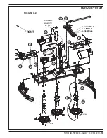
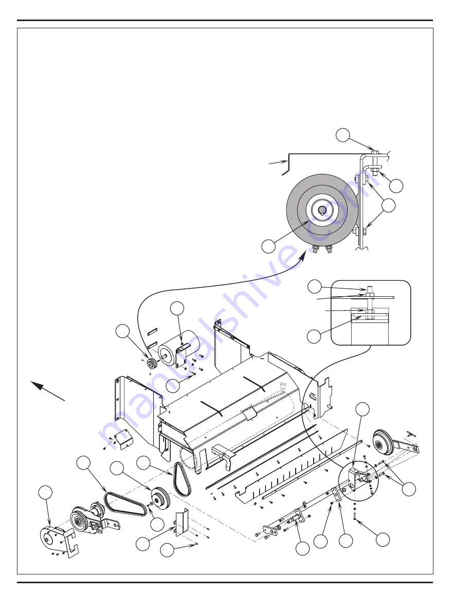
FIGURE 5.2
Summary of Contents for 56303000
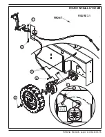
Page 17: ...FORM NO 56043096 Captor 4300B 4800B 15 FRONT WHEEL SYSTEM FIGURE 3 1...
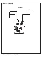
Page 20: ...18 FORM NO 56043096 Captor 4300B 4800B HYDRAULIC SYSTEM FIGURE 4 3...
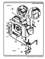
Page 33: ...FORM NO 56043096 Captor 4300B 4800B 31 SOLUTION SYSTEM FIGURE 7 1...
Page 39: ...FORM NO 56043096 Captor 4300B 4800B 37 SQUEEGEE SYSTEM FIGURE 10 1...
Page 41: ...FORM NO 56043096 Captor 4300B 4800B 39 SQUEEGEE SYSTEM FIGURE 10 2...
Page 45: ...FORM NO 56043096 Captor 4300B 4800B 43 WIRING SCHEMATIC before SN 1767238 ELECTRICAL SYSTEM...
Page 50: ......


