FORM NO. 56043096 - Captor
™
4300B, 4800B -
23
SWEEPING SYSTEM
SIDE BROOM MOTOR REMOVAL
1
Lower the side broom(s). Note: The main broom must be first lowered to allow the side brooms to be lowered.
2
Raise hopper to a comfortable work position (eye level). Then remove the side broom and disconnect the motor connector to the motor that
needs to be serviced.
3
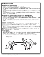
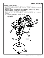
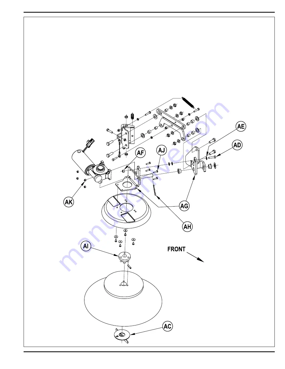
See Figure 5.5. Remove the (1)
(AD)
Screw,
(AE)
Washer and
(AF)
Nut that fasten the 2 broom bracket weldments
(AG)
together.
4
Remove
(AH)
Hairpin that fastens the 2-broom bracket weldment
(AG)
together.
5
Twist and pull the side broom motor assembly to separate it from the broom bracket weldment.
6
Place motor on a flat surface and remove the
(AI)
Hub. NOTE: The use of a spring pin in the motor shaft.
7
Remove the 4
(AJ)
Screws and
(AK)
Nuts that secure the motor to the broom bracket weldment. Then remove the motor for service or
replacement.
8
Install a serviced or new motor by following the above steps in reverse order.
FIGURE 5.5
Summary of Contents for 56303000
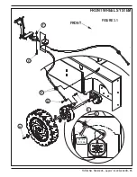
Page 17: ...FORM NO 56043096 Captor 4300B 4800B 15 FRONT WHEEL SYSTEM FIGURE 3 1...
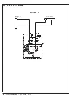
Page 20: ...18 FORM NO 56043096 Captor 4300B 4800B HYDRAULIC SYSTEM FIGURE 4 3...
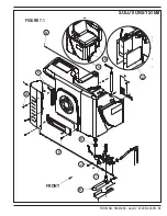
Page 33: ...FORM NO 56043096 Captor 4300B 4800B 31 SOLUTION SYSTEM FIGURE 7 1...
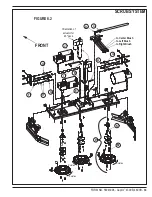
Page 39: ...FORM NO 56043096 Captor 4300B 4800B 37 SQUEEGEE SYSTEM FIGURE 10 1...
Page 41: ...FORM NO 56043096 Captor 4300B 4800B 39 SQUEEGEE SYSTEM FIGURE 10 2...
Page 45: ...FORM NO 56043096 Captor 4300B 4800B 43 WIRING SCHEMATIC before SN 1767238 ELECTRICAL SYSTEM...
Page 50: ......


