24
- FORM NO. 56043096 - Captor
™
4300B, 4800B
SWEEPING SYSTEM
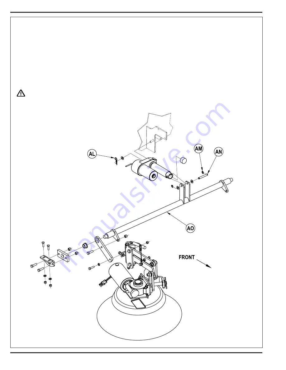
SIDE BROOM LIFT ACTUATOR MOTOR REPLACEMENT
Removal
1
Place the side brooms in the lowered position if possible or blocking underneath the brooms to remove weight from the lift linkage.
2
Open hopper cover, set cover prop rod, remove hopper filter, and latch filter rack. Then remove the hopper access panel held in-place by (11)
Philips head screws.
3
Disconnect the lift actuator motor wiring harness connector.
4
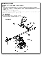
See Figure 5.6. Next remove the Hairpin
(AL)
from its mount pin.
5
Remove both the front Retainer Ring
(AM)
and the Mount Pin
(AN)
that attaches the actuator drive tube to the Lifting Shaft Weldment
(AO)
.
Then pull out the lift motor to complete its removal from the machine.
CAUTION!
See Instruction on setting the lift Actuator Motor before reinstalling.
6
To reinstall follow the above directions in reverse order and test for proper operation.
FIGURE 5.6
Summary of Contents for 56303000
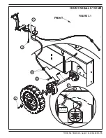
Page 17: ...FORM NO 56043096 Captor 4300B 4800B 15 FRONT WHEEL SYSTEM FIGURE 3 1...
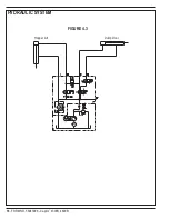
Page 20: ...18 FORM NO 56043096 Captor 4300B 4800B HYDRAULIC SYSTEM FIGURE 4 3...
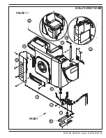
Page 33: ...FORM NO 56043096 Captor 4300B 4800B 31 SOLUTION SYSTEM FIGURE 7 1...
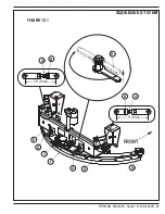
Page 39: ...FORM NO 56043096 Captor 4300B 4800B 37 SQUEEGEE SYSTEM FIGURE 10 1...
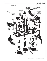
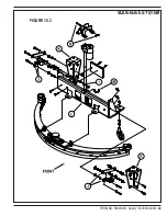
Page 41: ...FORM NO 56043096 Captor 4300B 4800B 39 SQUEEGEE SYSTEM FIGURE 10 2...
Page 45: ...FORM NO 56043096 Captor 4300B 4800B 43 WIRING SCHEMATIC before SN 1767238 ELECTRICAL SYSTEM...
Page 50: ......


