

28
- FORM NO. 56043096 - Captor
™
4300B, 4800B
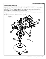
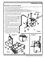
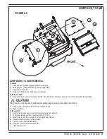
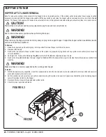
HOPPER SYSTEM
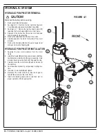
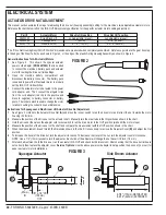
HOPPER LIFT CYLINDER REMOVAL
Note: To remove the cylinder it is necessary for the hopper to be in the raised position. If the cylinder will not raise under its own power it will be
necessary to press and hold the hopper raise switch with the key switch on and raise the hopper with an overhead hoist or some other alternate
method. The reason the hopper switch needs to be activated is to turn on the hydraulic solenoid cartridge to allow the cylinder oil to return to tank.
CAUTION!
There will be oil in cylinder and hoses, be prepared to plug hoses and recover cylinder oil.
WARNING!
Use common sense safety practices when performing this repair.
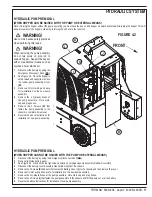
WARNING!
When removing the hopper cylinder do not rely solely on prop rod to support hopper. Support the hopper with some additional means
such as overhead hoist, stands etc.
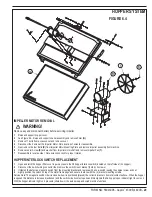
To Remove:
1
Raise the hopper and pull the safety prop rod into position then lower hopper until the rod is secure.
2
Disconnect the battery.
3
Remove the two hydraulic hopper cylinder hoses at the cylinder be prepared to plug hoses and cap cylinder connections (mark hoses for
correct installation).
4
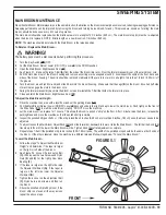
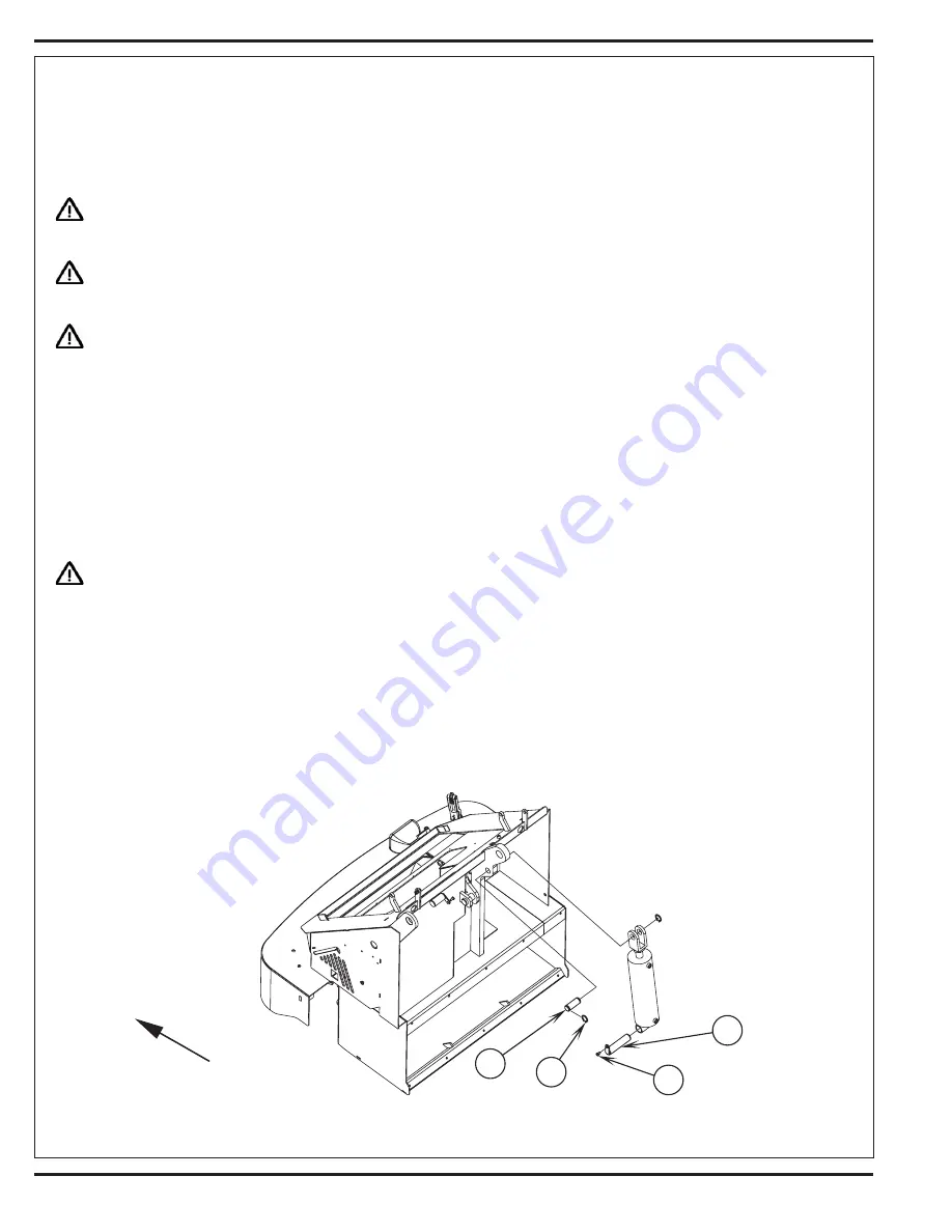
See Figure 6.3. Remove the Retaining Ring
(M)
from the Rod Pin
(N)
and completely remove the pin.
5
Remove the Screw
(O)
that fastens the lower Hinge Pin Weldment
(P)
to the chassis then pry pin to the side then carefully remove cylinder from
machine.
WARNING!
Make sure hopper is securely supported before working under hopper.
To Install:
1
With the hopper securely supported, mount the cylinder piston end to the chassis and pry the pin weldment back into position and secure in
place with previously removed screw.
2
Pull the cylinder rod end out until you are able to align (match up) the cylinder rod clevis to hopper mount install the pin and retaining rings to
secure the cylinder rod end to the hopper.
3
Reconnect the two hoses to the appropriate cylinder ports.
4
Check for proper operation and leaks.
FIGURE 6.3
Summary of Contents for 56303000
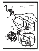
Page 17: ...FORM NO 56043096 Captor 4300B 4800B 15 FRONT WHEEL SYSTEM FIGURE 3 1...
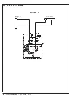
Page 20: ...18 FORM NO 56043096 Captor 4300B 4800B HYDRAULIC SYSTEM FIGURE 4 3...
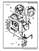
Page 33: ...FORM NO 56043096 Captor 4300B 4800B 31 SOLUTION SYSTEM FIGURE 7 1...
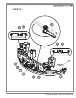
Page 39: ...FORM NO 56043096 Captor 4300B 4800B 37 SQUEEGEE SYSTEM FIGURE 10 1...
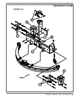
Page 41: ...FORM NO 56043096 Captor 4300B 4800B 39 SQUEEGEE SYSTEM FIGURE 10 2...
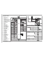
Page 45: ...FORM NO 56043096 Captor 4300B 4800B 43 WIRING SCHEMATIC before SN 1767238 ELECTRICAL SYSTEM...
Page 50: ......


