


10
9098827000(2)2010-12
SC3000 26” Disc / 28” Cyl.
ENGLISH
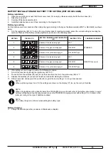
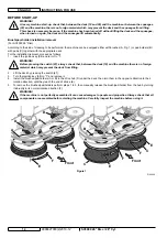
INSTRUCTIONS FOR USE
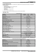
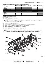
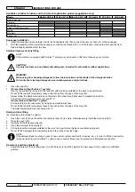
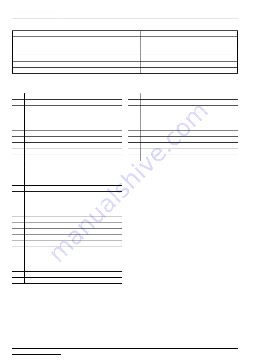
Technical data for machines with cylindrical brush deck
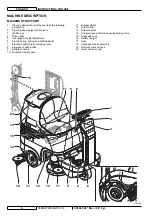
Description
28” Cyl.
Cylindrical brush size (diameter x length)
5.7 x 27.2 in (145 x 690 mm)
Weight without batteries and with empty tanks
396.8 lb (180 kg)
Maximum weight with batteries, full tanks and operator (75 kg) (GVW)
994.3 lb (451 kg)
Cylindrical brush motor power
2 x 0.8 HP (2 x 600 W)
Cylindrical brush speed
720 rpm
Cylindrical brush pressure
77.1 lb (35 kg)
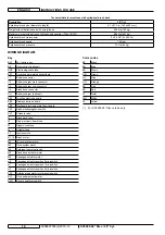
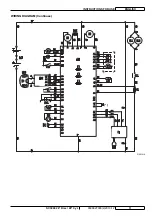
WIRING DIAGRAM
Key
BAT
24 V battery box
BE
Flashing light (optional)
BRK
Electromagnetic brake
BZ1
Reverse gear warning buzzer/horn
C1
Battery connector
C2
Battery charger main connector
C3
Battery charger sub-connector
C4
Brush deck connector
CH
Battery charger (optional)
EB1
Function electronic board
EB2
Display electronic board
EB3
Dashboard instrument electronic board
ES1
Brush electromagnetic switch
EV1
Solenoid valve
F1
Brush deck fuse
F2
Main electronic board fuse
F3
Signal circuit fuse
F4
Actuator fuse
K1
Ignition switch
M1.1,2 Brush motor
M2
Vacuum system motor
M3
Drive system motor
M4
Detergent pump (optional)
M5
Brush deck actuator motor
M6
Squeegee actuator motor
m0
Squeegee actuator position 0 microswitch
m1
Squeegee actuator position 1 microswitch
m2
Squeegee actuator position 2 microswitch
PR1
Solution/clean water level pressure switch
RV1
Drive pedal potentiometer
SW1
Driver’s seat microswitch
Color codes
BK
Black
BU
Blue
BN
Brown
GN
Green
GY
Grey
OG
Orange
PK
Pink
RD
Red
VT
Violet
WH
White
YE
Yellow
For SC3000 26” Disc version only
(*)
Summary of Contents for 9087266020
Page 2: ......


