background image

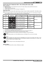
SC3000 26” Disc / 28” Cyl.

9098827000(2)2010-12

7

INSTRUCTIONS FOR USE

ENGLISH

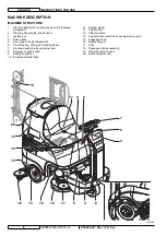
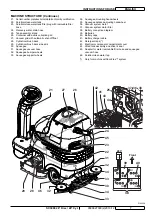
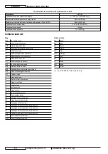
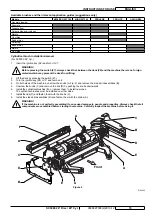
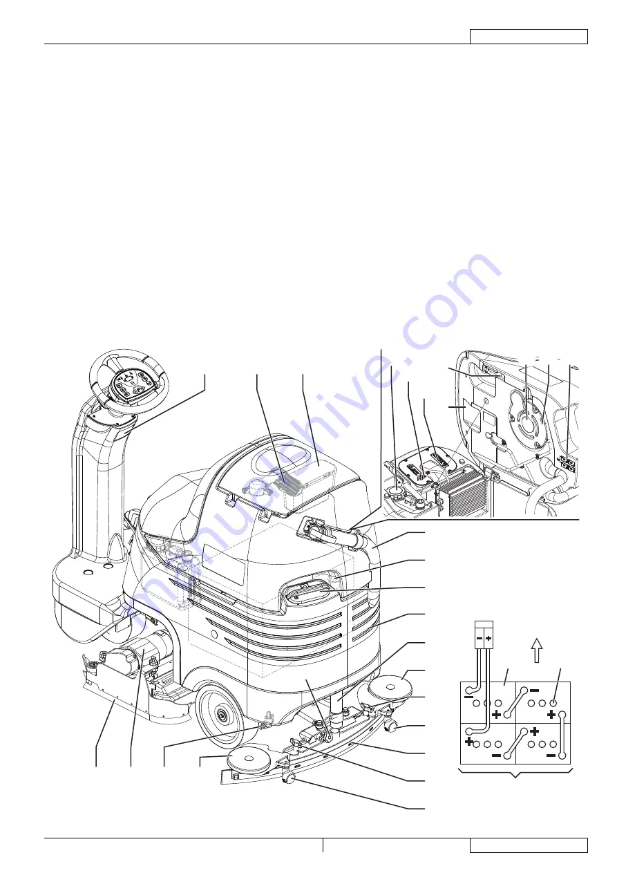
MACHINE STRUCTURE (Continues)

Serial number plate/technical data/conformity certifi cation

21. 

Solution/clean water tank

22. 

Solution/clean water tank fi ller plug with removable fi ller 

23. 

hose
Recovery water drain hose

24. 

Tank assembly stand

25. 

Container with debris collection grid

26. 

Vacuum grid with automatic shut-off fl oat

27. 

Cylindrical brush deck

28. 

Cylindrical brush deck side skirt

29. 

Squeegee

30. 

Squeegee vacuum hose

31. 

Squeegee bumper wheels

32. 

Squeegee support wheels

33. 

Squeegee mounting handwheels

34. 

Squeegee balance adjusting handwheel

35. 

Vacuum system motor

36. 

Vacuum system motor fi lter

37. 

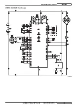
Battery connection diagram

38. 

Batteries

39. 

Battery caps

40. 

Battery charger cable

41. 

Detergent tank (*)

42. 

Electronic component compartment cover

43. 

Lifted tank assembly and driver’s seat

44. 

Adapter for water removable fi ller hose and squeegee 

45. 

vacuum hose
Solution/clean water tap

46. 

Only for machine with EcoFlex™ system

(*) 

Front

24V

21

27

26

25

42

41

43

44

37 36 38

35

33

34

30

33

34

32

31

22

23

45

24

29

38

40

39

32

28

46

P100359

Summary of Contents for 9087266020

Page 1: ...RUCTIONS D UTILISATION INSTRUCCIONES DE USO INSTRU ES DE USO Advance models 9087266020 26 Disc Charger 9087267020 26 Disc EcoFlex Charger 9087268020 28 Cyl Charger 9087269020 28 Cyl EcoFlex Charger EN...

Page 2: ......

Page 3: ...TERY TYPE SETTING WET OR GEL AGM 13 BEFORE START UP 14 MACHINE START AND STOP 17 MACHINE OPERATION SCRUBBING DRYING 18 TANK EMPTYING 20 AFTER USING THE MACHINE 21 PUSHING TOWING THE MACHINE 21 FIRST P...

Page 4: ...ndicated by the first two figures of the machine serial number This information is useful when requiring machine spare parts Use the following table to write down the machine identification data MACHI...

Page 5: ...y and take all necessary precautions to safeguard people and property The operator s cooperation is essential in order to prevent injury No accident prevention program is effective without the total c...

Page 6: ...e Do not close a door on the battery charger cable or pull the battery charger cable around sharp edges or corners Do not run the machine on the battery charger cable Keep the battery charger cable aw...

Page 7: ...the electromagnetic brake must be disengaged After moving the machine manually engage the electromagnetic brake again Do not use the machine when the electromagnetic brake handwheel is screwed down W...

Page 8: ...height adjustment 5 Front steering driving and braking wheel 6 Electromagnetic brake unlocking lever 7 Emergency push button 8 Battery connector 9 Brush pad holder deck 10 Bumper wheel 11 Solution fi...

Page 9: ...e skirt 29 Squeegee 30 Squeegee vacuum hose 31 Squeegee bumper wheels 32 Squeegee support wheels 33 Squeegee mounting handwheels 34 Squeegee balance adjusting handwheel 35 Vacuum system motor 36 Vacuu...

Page 10: ...ush pad holder deck and squeegee lifting lowering LED 68 indicator EcoFlex activation deactivation lever 69 EcoFlex system LED indicator 70 LED on EcoFlex system on LED flashing EcoFlex system overrid...

Page 11: ...power 0 4 HP 300 W Maximum speed 3 7 mph 6 km h Maximum gradient when working 2 1 14 Sound pressure level at workstation ISO 11201 ISO 4871 EN 60335 2 72 LpA 65 dB A 3 dB A Machine sound pressure lev...

Page 12: ...Battery charger sub connector C4 Brush deck connector CH Battery charger optional EB1 Function electronic board EB2 Display electronic board EB3 Dashboard instrument electronic board ES1 Brush electr...

Page 13: ...SC3000 26 Disc 28 Cyl 9098827000 2 2010 12 11 INSTRUCTIONS FOR USE ENGLISH WIRING DIAGRAM Continues P100361A...

Page 14: ...rotection caps supplied with the machine The machine requires 4 6 V batteries connected according to the diagram 38 The machine can be supplied in one of the following modes Batteries WET or GEL AGM a...

Page 15: ...shes of the yellow warning light GEL EXIDE type 4 2 flashes of the red warning light WET REDUCED see note 5 2 flashes of the green warning light GEL AGM 6 2 flashes of the yellow warning light GEL EXI...

Page 16: ...eed as follows Insert the ignition key 58 and turn it to I 1 WARNING Before pressing the switch 67 always check that between the deck 10 and the machine there is no foreign material which may prevent...

Page 17: ...deck from lifting Lift the deck by pressing the switch 67 2 Turn the ignition key 58 to 0 and remove it 3 On both sides of the machine unscrew the knobs A Fig 2 and remove the side skirt assemblies B...

Page 18: ...the tank 22 with a solution suitable for the work to be performed Do not fill the tank 22 completely leave a few inches from the edge of the plug 23 Always follow the dilution instructions on the labe...

Page 19: ...y when the operator is on the driver s seat NOTE The machine is equipped with an anti skid safety system LED 72 flashing that reduces the speed when turning and when the machine tilts laterally irresp...

Page 20: ...oncentration in the solution dispensed from the system always corresponds to level 1 In order to temporarily obtain a stronger concentration press the EcoFlex switch or disable the EcoFlex system see...

Reviews: