FORM NO. 56043111 - Adhancer
™
-
65
APPENDIX
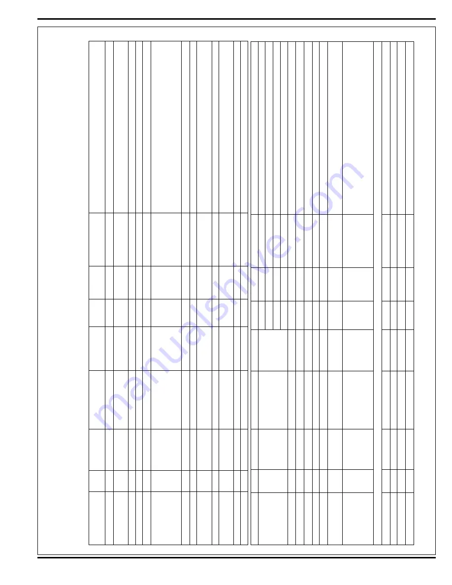
MAIN CONTROLLER I/O T
ABLES
Ladder Diagram: 56016748; PCB Schematic: 56316123; I/O Schematic: 563161
12
B- = Battery –
B+ = B
Designation
Pin ID
W
ire ID/Color
Description
Signal
Characteristic
Nominal
Value
Reference
To
:
Range
Comments
Output
J1-3
RED/WHT
AXP
Board Power
VDC
+5V
B- (Gnd)
Supplied by control board
Input
J1-4
ORN/BLU
Speed Control Status
VDC
-36V
B+
37.6 - 30.6V
Pulsed signal equal to the fault code
fl
ashed by the speed control
built-in status LED
Input
J1-5
RED/BLK
Forward/Reverse
VDC
-36V
B+
37.6 - 30.6V
Machine is not in neutral
Input
J1-6
BLU/BLK
Direction
VDC
-36V
B+
37.6 - 30.6V
Machine is traveling in reverse
Ground
J1-7
BLK
Power Supply
VDC
-36V
B+
37.6 - 30.6V
Output
J1-8
GRN/BLK
Solution Pump
PWM V
oltage
B- (Gnd)
+/- 3V depending
on battery voltage
5000 Hz freq. (See Figure 1 for voltage measurement locations.)
One bar on solution
fl
ow indicator = 13% duty cycle
≈
31.3V
Two bars on solution
fl
ow indicator = 38% duty cycle
≈
22.3V
Solution pump of
f = 0% duty cycle
≈
36V
Ground
J1-9
BLK
Power Supply
VDC
-36V
B+
37.6 - 30.6V
Output
J1-1
1
RED/GRN
Solution Solenoid
VDC
-36V
B-
37.6 - 30.6V
Solution Solenoid is
Active
Output
J1-12
BLK/YEL
Vacuum Contactor
PWM V
oltage
B- (Gnd)
+/- .7V depending
on battery voltage
5000 Hz freq, 80% duty cycle V
acuum Motor is
Active
(
≈
6.9V), 0% duty cycle V
acuum Motor is of
f (
≈
36V)
Power
J1-13
BRN
Power Supply
VDC
+36V
B- (Gnd)
37.6 - 30.6V
Key is switched on
Output
J1-14
VIO/BLK
Brush Contactor
PWM V
oltage
+7.2V
B- (Gnd)
+/- .7V depending
on battery voltage
5000 Hz freq, 80% duty cycle Brush Motor is
Active (
≈
6.9V),
0% duty cycle Brush Motor is of
f (
≈
36V)
Output
J2-1
VIO/YEL
Actuator
VDC
36V
J2-8
37.6 - 30.6V
+36V while lowering, -36 while raising
Output
J2-2
BLK
AXP
Board Ground
VDC
-36V
B+
37.6 - 30.6V
Supplied by control board
Input
J2-3
BRN/BLK
AXP
Detergent Ratio
Analog V
oltage
B- (Gnd)
5.0 - 1.0V
Controlled by detergent ratio sensor
Input
J2-4
GRA/WHT
Recovery T
ank
Full
Switch
VDC
-36V
B+
37.6 - 30.6V
Recovery tank is not full (
fl
oat switch normally closed)
-31V
B+
31.6 - 25.6V
Recovery tank is full (
fl
oat switch normally closed)
-36V
B+
37.6 - 30.6V
Recovery tank is full (
fl
oat switch normally open)
-31V
B+
31.6 - 25.6V
Recovery tank is not full (
fl
oat switch normally open)
Input
J2-5
WHT/GRA
Brush Current Sense
Analog V
oltage
B- (Gnd)
0.20 - 0.05V
Brush motors are active
Ground
J2-6
BLK
Power Supply
VDC
-36V
B+
37.6 - 30.6V
Power
J2-7
BRN
Power Supply
VDC
+36V
B- (Gnd)
37.6 - 30.6V
Output
J2-8
WHT/GRN
Actuator
VDC
36V
J2-1
37.6 - 30.6V
-36V while lowering, +36 while raising
Ground
J2-9
BLK
Power Supply
VDC
-36V
B+
37.6 - 30.6V
Input
J2-10
ORN
Vacuum Current
Sense
Analog V
oltage
+0.12V
B- (Gnd)
0.13 - 0.1
1V
Vacuum motor is active
Output
J2-1
1
YEL/VIO
Chemical/Detergent
Pump
PWM V
oltage
B- (Gnd)
Contact Engineering for troubleshooting information. Detergent
pump is active: line alternates between 36V and a PWM signal
5000 Hz freq, 67% duty cycle (
≈
12V). Detergent pump is of
f:
DC V
oltage (
≈
36V)
AXP
Control Board;
AXP
PCB Schematic: 56314929-B
Input
J1-1
RED/WHT
AXP
Board Power
Voltage
+5V
B- (Gnd)
Supplied by control board
Input
J1-2
BLK
AXP
Board Ground
Voltage
-24V
B+
25.5 - 20.4V
Supplied by control board
Not used
J1-3
Not used
Output
J1-4
BRN/BLK
AXP
Detergent Ratio
Analog V
oltage
B- (Gnd)
5.0 - 1.0V
Signal is sent to main control board
Summary of Contents for Adhancer 56316001(W32-C)
Page 1: ...7 08 FORM NO 56043111 SERVICE MANUAL Models 56316000 W28 C 56316001 W32 C Adhancer...
Page 2: ......
Page 7: ...FORM NO 56043111 Adhancer 5 TECHNICAL SPECIFICATIONS...
Page 25: ...FORM NO 56043111 Adhancer 23 SCRUB SYSTEM FIGURE 2...
Page 51: ...FORM NO 56043111 Adhancer 49 FIGURE 4...
Page 53: ...FORM NO 56043111 Adhancer 51 FIGURE 5 ELECTRICAL SYSTEM...
Page 59: ...FORM NO 56043111 Adhancer 57 FIGURE 6 ELECTRICAL SYSTEM...
Page 68: ......
Page 74: ......


