1316-900 Revision AA
10kW Precision Calorimeter
21
General
Warm Up and Stabilization
Permit the unit to operate at a minimum of approximately 2 hours prior to application of AC or
RF power once everything is powered on and the chillers are engaged. Manual dwell times at
desired calibration power levels should be > 10 minutes (the temp control loop needs this
minimum time to react and settle) and it is suggested to be at least 20 minutes for best accuracy.
AC Substitution
Calibration procedures are based on AC substitution. A source of AC power is applied to the load
to simulate the heating effect of the unknown RF power and is measured using readily available
AC power sources and measuring equipment. The accuracy of the AC power meter (known to be
extremely accurate) can then be transferred to the RF measurement since a well-designed RF load
will respond nearly identically to either AC or RF power up to a specified high frequency limit.
Many calorimeters in use today express accuracy as a percentage of full scale, less load error.
Only the power that is absorbed by the load is measured and displayed. All other power
(reflected, etc.) is considered part of the load error and is not measured. This may be convenient
for the manufacturer, but to achieve a more precise measurement, this load error can be
characterized by determining the reflection coefficient of the RF load as a function of frequency
and compensating for it at the frequency of interest. The 1316 automatically compensates for this
error term by storing the RF load reflection data in memory and then applying it as a frequency
correction term to obtain the final calibrated RF answer in watts.
Correction of Error Terms
All of the error term parameters collected and analyzed by the 1316 are incorporated into four
separate initialization files comprised of one file representing the actual reflection coefficient of
the load, one characterization file that defines constants and dynamic correction terms specific to
the design/construction of the calorimeter, one file representing the efficiency of the RF load to
convert the electrical energy into thermal energy as a function of power and frequency, and one
file of calibration constants defining the slope and intercept points of a piecewise linear
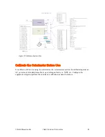
approximation to a calibrated AC reference power source. These files are shown geographically
in Figure 16 and are uploaded to the 1316 prior to making calibrated RF measurements.
Defining the parameters of the error terms contained within these files allows the system
firmware to be flexible and adapt easily to situations where the load or fluid components may
need to be changed in the future. When the calorimeter makes its final calculation of either
calibrated AC or RF power, applicable error parameters are called and used to refine the final
displayed power.

