Wiring Diagrams for Multiple
Analog Outputs
POSSIBLE WIRING FOR DIFFERENTIAL
VOLTAGE INPUTS
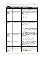
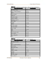
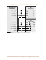
In many cases, differential voltage inputs exist.
shows the wiring using
a multi-core cable with a 7 Ω resistance per wire (for example, 7 Ω corresponds to
a 100 m [328′10″] length cable with 0.25 mm
²
wire cross-section) between the multi-
analog box and the programmable logic controller (PLC). Connect the separately
routed voltage input ground to the high resistance minus input of the differential
voltage input.
This example shows simple, non-differential current inputs. In the case of differential
current inputs, connect the ground for the current inputs to the negative inputs of the
current inputs.
You can wire a combination of simple voltage inputs and differential current inputs.
In this case, connect the voltage input ground to the corresponding ground clamp and
connect the current input ground to the negative inputs of the current inputs.
☞
Important
Be sure that the differential current inputs are sufficiently highly resistive.
Impac
®
Series 600 Pyrometer
Appendix
H
57010228-00C
Wiring Diagrams for Multiple Analog Outputs
H‑1

