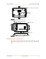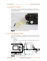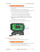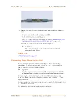
Use either a connection cable from AE or use a customer-supplied cable to connect
directly to the terminal block on the converter box.
To Connect to an RS-485 Interface
1. Connect the A1 wire to pin 3 (DIG 3).
2. Connect the B1 wire to pin 4 (DIG 4).
3. Connect the shield wire to pin 5 (DIG 5).
4. Connect the A2 wire to pin 8 (DIG 8).
5. Connect the B2 wire to pin 9 (DIG 9).
6. Connect the cable to the PC via the serial port.
CONNECTING TO PROFINET
To connect to PROFINET, only use Ethernet-patch cables in CAT5e quality in
connection with an M12 connector system (D-type). An ESI file is provided with
the converter box that contains all the required controller-pyrometer parameters
for integrating into a PROFINET network. After importing the file, all relevant
pyrometer data is available to the controller.
Default configuration (changeable via Infra600 through a WebServer call):
• IP address: 0.0.0.0
• Subnet mask: 0.0.0.0
• Device name: pyrometer
To Connect to PROFINET
1. Connect the RxD− wire (blue wire) to pin 3 (DIG 3).
2. Connect the RxD+ wire (white wire) to pin 4 (DIG 4).
3. Connect the TxD− (orange wire) to pin 8 (DIG 8).
4. Connect the TxD+ wire (yellow wire) to pin 9 (DIG 9).
5. Connect the cable to the PC via the Ethernet port.
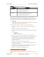
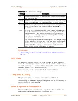
6. Check the four PROFINET LED status indicators on the front of the pyrometer
to verify that the setup is correct and functional.
◦ If
LED 1
is off, communication is good.
◦ If
LED 1
is blinking red, there was an internal bus failure, configuration
problem, or an error at the PROFINET initialization.
◦ If
LED 2
is off, there is no communication.
◦ If
LED 2
is solid green (constant), the communication between Master and
pyrometer is working and complete process data traffic is active.
◦ If
LED 2
is blinking green, the system is in configuration mode and
PROFINET is initialized, but no process data traffic is possible.
Advanced Energy
®
Impac
®
Series 600 Pyrometer
57010228-00C
Installation, Setup, and Operation
3‑8

