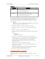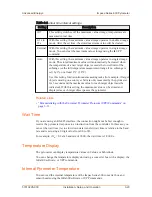
Table 3‑2. Clear time interval settings
Setting
Description
Off
This setting switches off the maximum value storage; temperatures are
measured in real time.
0.1 s to
25 s
With this setting, the maximum value storage operates in double storage
mode. After the set time, the stored maximum value will be cleared.
External With this setting, the maximum value storage operates in single storage
mode. You can clear the maximum value storage using the
lx
UPP
command.
Auto
With this setting, the maximum value storage operates in single storage
mode. The stored maximum value will automatically be cleared when
the temperature of a new target object exceeds the lower limit of the
subrange (or the full temperature measurement range if no subrange is
set) by 1% or at least 2°C (1.8°F).
Use this setting for discontinuous measuring tasks (for example, if target
objects moving on a conveyer belt are only measured by the pyrometer
for 3 seconds and the maximum value for each target object must be
indicated). With this setting, the maximum value can be stored and
displayed as each target object passes the pyrometer.
Related Links
• “Parameterizing with the Universal Pyrometer Protocols (UPP) Commands” on
Wait Time
If you are using an RS-485 interface, the connection might not be fast enough to
receive the pyrometer response to an instruction from the controller. In this case, you
can set the wait time (t
w
) to slow down data transfer (wait time is relative to the baud
rate and is set using a 2-digit value from 00 to 99).
For example, if t
w
= 02 at a baud rate of 9600, the wait time is 2/9600 s.
Temperature Display
The pyrometer can display temperature values in Celsius or Fahrenheit.
You can change the temperature display unit using a converter box with a display, the
Infra600 software, or UPP commands.
Internal Pyrometer Temperature
You can read the internal temperature of the Impac Series 600 converter box and
sensor heads using the Infra600 software or UPP commands.
Advanced Energy
®
Impac
®
Series 600 Pyrometer
57010228-00C
Installation, Setup, and Operation
3‑20

