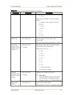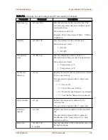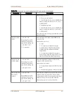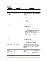
+Input 1
−Input 1
Input 2
Input 3
Input 4
Output 1
Output 2
Output 3
Output 4
Input 5
Input 6
Input 7
Output 5
Output 6
Output 7
Input 8
Common
Output 8
Common
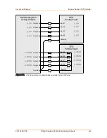
Multi-Analog Box
Analog Outputs
SPS
Analog Inputs
Figure H‑1. Wiring example for differential voltage inputs
POSSIBLE WIRING FOR SIMPLE, NON
DIFFERENTIAL VOLTAGE INPUTS
In this case, if only simple, non-differential voltage inputs are in place and the
voltage and current inputs have only one common ground connection, you can use
an alternative voltage input. The separate voltage input ground is then applied to this
additional voltage input.
shows the wiring using a multi-core cable with
a 7 Ω resistance per wire (for example, 7 Ω corresponds to a 100 m [328′10″] length
cable with 0.25 mm
²
wire cross-section) between the multi-analog box and the PLC.
In this case, note that the incoming voltage can become negative in relation to the
current input ground. Therefore, you must be able to measure negative voltages in
the inputs. You should measure the voltages as synchronously as possible in order to
avoid measuring errors based on signal changes.
Advanced Energy
®
Impac
®
Series 600 Pyrometer
57010228-00C
Wiring Diagrams for Multiple Analog Outputs
H‑2


