background image


O

PE

RATI

O

N M

ANUAL


E

2

T QUASAR Flare Monitors 

M8100PM-EXP • M8100FM-EXP • M8100SM-EXP 


Summary of Contents for LumaSense Technologies E2T QUASAR M8100FM-EXP

Page 1: ...OPERATION MANUAL E2 T QUASAR Flare Monitors M8100PM EXP M8100FM EXP M8100SM EXP...

Page 2: ...E2 T is a trademark of LumaSense Technologies All other trademarks are trademarks registered trademarks and or service marks of their respective holders Service Centers LumaSense Technologies Inc Nor...

Page 3: ...velength 2 color 13 2 4 2 PM Pilot Monitor s Flame Sensitive Wavelength 14 2 4 3 FM Flare Monitor s Flame Sensitive Wavelength 14 2 5 Quick Installation Procedure 14 3 Mechanical Installation 17 3 1 G...

Page 4: ...ication 33 5 1 7 Relay Contacts 33 5 1 8 Delay Adjust 34 5 1 9 Milliamp Output mA mA 34 6 Operating the M8100FM EXP 35 6 1 Start Up Operation Checklist Flare Monitor FM 36 6 1 1 Getting Started 36 6 1...

Page 5: ...tics 52 10 Safety Assurances and Precautions 53 10 1 Hazardous Environment Safety 53 10 2 Electrical Service Protection 53 10 2 1 Over Current Protection Service Switch 53 10 2 2 Over Voltage Protecti...

Page 6: ...E2 T QUASAR Flare Monitors Operation Manual General vi To ensure consistent document formatting this page was intentionally left blank...

Page 7: ...g Denotes information critical to avoiding personal injury such as when an electrical hazard is present When this symbol is found on the instrument it indicates a potential hazard Consult the document...

Page 8: ...rmation and notes for handling maintenance and cleaning of this instrument are offered according to the best of our knowledge and experience LumaSense Technologies is not liable for any damages that a...

Page 9: ...M8100 EXP Be sure to reference Chapter 10 Safety Assurances and Precautions before you begin installation 1 5 Service Request Repair or Support Contact LumaSense Technologies Technical Support in cas...

Page 10: ...ng package exterior If no RMA is indicated shipment will not be accepted Send RMA Shipments to your nearest technical service center Customers in North America should send RMA Shipments to Santa Clara...

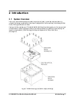
Page 11: ...ts designed for continuous duty monitoring of Pilot Flame Flaring and Smoke on Flares The heart of the LumaSense E2 T QUASAR M8100 EXP Flare Monitoring System is the non contact infrared Electro Optic...

Page 12: ...g base air purge tube and swivel mount An optional adjustable pedestal stand allows for easy mounting 2 2 System Features Features of the QUASAR M8100 EXP Flare Monitoring System are as follows Explos...

Page 13: ...M FM 4 or 20mA circuit outputs 4mA or 20mA depending on a preset signal level Standard output provides 4mA with a flame present 20mA without a flame present This is a switched output SM mA circuit out...

Page 14: ...service electrical equipment designed for areas classified as hazardous At no time should the cover be removed unless power is switched off first When it is necessary to service the instrument with t...

Page 15: ...ptable b Connect the instrument loops and alarm outputs i Connect the lines as needed for Normal Open N O or Normal Closed N C relay to the corresponding locations on TB2 ii Connect the mA lines to th...

Page 16: ...E2 T QUASAR Flare Monitors Operation Manual Introduction 16 To ensure consistent document formatting this page was intentionally left blank...

Page 17: ...ecautions 3 2 Sight Assessment Care must be taken during installation to ensure that the sun will not be seen through the optical sight path in any season or time of day This requires that the instrum...

Page 18: ...Smoke Monitor SM Sighting Recommended installation distance from the base of the stack is at least 1 to 2 times the stack height The maximum vertical angle for sighting the monitor is 45 above horizo...

Page 19: ...3 4 Cooling Requirements If ambient temperatures in excess of 120 F 50 C are anticipated during the operation of the QUASAR M8100 EXP cooling will be required by one of the following two methods 3 4...

Page 20: ...rough a regulator or needle valve capable of sustaining 1 SCFM flow rate from a 20 psig or greater supply is required to keep the lens clean 3 6 Target Size and Focusing Range The target size of the Q...

Page 21: ...E2 T QUASAR Flare Monitors Operation Manual Mechanical Installation 21 1 Eyepiece Lens with Reticle 2 Focus Adjust and Lens Locking Screw 3 Objective Lens...

Page 22: ...E2 T QUASAR Flare Monitors Operation Manual Mechanical Installation 22 To ensure consistent document formatting this page was intentionally left blank...

Page 23: ...the housing explosion proof packing gland fittings to the hard conduit or junction box to enable movement of the unit on the pedestal All power and signal connections are made on the Terminal Output...

Page 24: ...3 Cover Attachment Warning At no time should the cover be removed unless power is switched off first When it is necessary to service the instrument with the power applied ensure that proper safe envi...

Page 25: ...ation See Appendix A for Power and Fuse Requirements and Appendix E Engineering Drawing 613 816 Service Connections North American Connection as follows to TB1 AC Hot1 to terminal labeled L1 HOT AC Ho...

Page 26: ...per J2 is hardwired for 110 V AC and 24 V DC systems Refer to Appendix A for power and fuse requirements and Appendix E drawing 613 816 Service Connections 4 4 Connection for mA Output The mA current...

Page 27: ...e Set Point Relay The set point relay provides a dry contact closure with a normally open and normally closed output The relay is rated 1 amp resistive to 120 V AC max Connect the relay to terminal TB...

Page 28: ...E2 T QUASAR Flare Monitors Operation Manual Electrical Installation 28 To ensure consistent document formatting this page was intentionally left blank...

Page 29: ...that the adjustments will produce the highest dynamic range This is achieved by setting the highest gain without putting the instrument into a self oscillation condition The delay setting is optimized...

Page 30: ...E2 T QUASAR Flare Monitors Operation Manual Operating the M8100PM EXP 30 Figure 7 Instrument Aiming Concept...

Page 31: ...r be removed unless the power is switch off first When it is necessary to service the instrument with the power applied ensure that proper safe environmental conditions exist and that such maintenance...

Page 32: ...t false alarms from varying conditions or wind Once the instrument is aimed at the pilot flame and the Three Way Switch is set to 100X adjust the Delay Pot item 9 to achieve the desired delay response...

Page 33: ...for noise amplification If noise amplification has stopped go to step 3 ii If noise continues return the Climate Compensation switch to its original setting and proceed to step 5 3 Verify that the ana...

Page 34: ...hould be approximately 4mA when the flame is present and the analog meter reads full scale The signal should read approximately 20mA when flame is lost with analog meter under 35 of scale Milliamp che...

Page 35: ...itor is designed to continuously monitor flared gases from remote locations up to mile 400 m away in nearly any climate condition while ignoring Pilot Flames This makes it ideal for confirming complia...

Page 36: ...er be removed unless the power is switch off first When it is necessary to service the instrument with the power applied ensure that proper safe environmental conditions exist and that such maintenanc...

Page 37: ...he Three Way Switch is set to 100X adjust the Delay Pot item 9 to achieve the desired delay response To verify settings simply block the sight path by covering the Objective lens item 8 and wait for t...

Page 38: ...ed confirm that the flame signal and not the noise is being amplified Check for noise application To check for Noise Amplification 1 Completely cover the objective lens 2 Ensure that the red LED activ...

Page 39: ...false alarms from temporary loss of signal due to wind 6 1 10 Milliamp Output mA mA Check the milliamp output signal at the instrument s Terminal Output board The signal should be approximately 4mA w...

Page 40: ...should light after the expected delay If this does not occur proceed to step 5 below 4 Verify that the analog meter reads at least 8 when the Flare is present The procedure is complete Do not proceed...

Page 41: ...rument provides relative smoke particulate level information rather than an absolute quantification Setup of the Smoke Monitor is most easily performed under the flare stack s normal operating conditi...

Page 42: ...E2 T QUASAR Flare Monitors Operation Manual Operating the M8100SM EXP 42 Figure 11 Instrument Aiming Concept...

Page 43: ...er be removed unless the power is switch off first When it is necessary to service the instrument with the power applied ensure that proper safe environmental conditions exist and that such maintenanc...

Page 44: ...alog meter Place your hand over the Objective lens The analog meter should drop to slightly above zero Note If the Flame normal operating conditions are not achievable for this adjustment refer to the...

Page 45: ...d the sixteen M8 x 1 25 socket head screws torque to 30in lbs 2 Supply positive air flow and pressure to the air connections 3 Verify that the temperature of the QUASAR M8100 EXP housing will not exce...

Page 46: ...6mA Blue plume 0 3 10mA Prevailing blue flame with 0 5 12mA occasional faint orange Intermittent light orange 0 6 0 7 13 14mA flame with puffs of light smoke FLARING GAS Continuous orange with smoke...

Page 47: ...e QUASAR M8100 EXP Without a clear optical path the infrared energy from a target cannot reach the detector If the lens becomes smeared smudged or otherwise dirty excessive attenuation of the signal m...

Page 48: ...physical damage If power is applied and the wheel will not rotate check to see if the wheel is hanging up on any obstruction Caution DO NOT attempt to bend the wheel or motor bracket Instead loosen t...

Page 49: ...dently burned in until a stable output is achieved Inspection and quality control procedures assure the highest standard of component reliability However electronic components do fail occasionally and...

Page 50: ...E2 T QUASAR Flare Monitors Operation Manual Troubleshooting 50 To ensure consistent document formatting this page was intentionally left blank...

Page 51: ...ed without affecting instrument performance are Replacement of MOV components on the power supply and Terminal Output boards Repairs to the Output terminal board heater assemblies interconnecting cabl...

Page 52: ...located within the electro optical package and will remain clean under normal conditions provided the enclosure remains sealed at all times with o rings in place LumaSense does not recommend cleaning...

Page 53: ...hazardous live condition in the event screws loosen Check and secure the safety ground connections just prior to lid closure When attaching the utility conduit ensure that at least five threads are e...

Page 54: ...d to expectations When wiring follow the local code regulations Secure the power input lines together after connection to the terminal block to prevent an accidental hazardous live condition in the ev...

Page 55: ...onal 115 Watts Fusing ELECTRONICS 115 250A T Time Lag 5x20 Little fuse type 218 250 220 125A T Time Lag 5x20 Little fuse type 218 125 24 V 1A T Time Lag 5x20 Little fuse type 218 001 6 882 480 Fuse 1...

Page 56: ...service inch NPT Mounting M 3 mounting fixture height adjustable pedestal with 360 swivel 70 to 70 vertical Torque Spec Lid Bolts 50in lbs 5 5 5N m Air View port purge 20psig min 1 SCFM Cooling For am...

Page 57: ...uping based on type testing Temperature code T4 maximum surface temperature will not exceed 135 C 275 F Pertinent when considering gas ignition temperatures that may come in contact Equipment Group II...

Page 58: ...ere a given location is classified as hazardous it should not be difficult to determine in which of the three classes it be longs Common sense and good judgment must prevail in classifying an area tha...

Page 59: ...d within closed containers or closed systems from which they can escape only in case of accidental rupture or breakdown of such containers or systems or in case of abnormal operation of equipment or 2...

Page 60: ...equent malfunctioning of handling or processing equipment and where combustible dust accumulations on in or in the vicinity of the electrical equipment may be sufficient to interfere with the safe dis...

Page 61: ...E2 T QUASAR Flare Monitors Operation Manual Appendix C Declaration of Conformity Certificate 61 Appendix C Declaration of Conformity Certificate...

Page 62: ...E2 T QUASAR Flare Monitors Operation Manual Appendix C Declaration of Conformity Certificate 62 ATEX KEMA Dekra Certificate Please contact the factory for a copy of the document...

Page 63: ...cur return shipping and freight charges The customer s end user s sole and exclusive remedy in the event of a perceived or real defect is herein and expressly limited to the correction of said defect...

Page 64: ...E2 T QUASAR Flare Monitors Operation Manual Appendix D Statement of Limited Warranty New Instruments 64 To ensure consistent document formatting this page was intentionally left blank...

Page 65: ...g Drawings 65 Appendix E Engineering Drawings Page Dwg Description 68 613 107 Isometric Assembly M8100 69 613 228 Isometric Assembly M8100PM EXP Mechanical Installation 70 613 812 Isometric Assembly M...

Page 66: ...E2 T QUASAR Flare Monitors Operation Manual Appendix E Engineering Drawings 66 Drawing 613 107 E2 T QUASAR M8100 EXP Appendix E...

Page 67: ...E2 T QUASAR Flare Monitors Operation Manual Appendix E Engineering Drawings 67 Drawing 613 228 E2 T QUASAR M8100 EXP Appendix E...

Page 68: ...E2 T QUASAR Flare Monitors Operation Manual Appendix E Engineering Drawings 68 Drawing 613 812 E2 T QUASAR M8100 EXP Appendix E...

Page 69: ...E2 T QUASAR Flare Monitors Operation Manual Appendix E Engineering Drawings 69 Drawing 613 816 E2 T QUASAR M8100 EXP Appendix E...

Page 70: ...E2 T QUASAR Flare Monitors Operation Manual Appendix E Engineering Drawings 70 To ensure consistent document formatting this page was intentionally left blank...

Page 71: ...ich 53 Over Voltage Protection 53 Protective Ground Connection 54 Transient Protection 54 Wiring 54 Electro Optical package 11 12 Explosion Proof Housing 8 F Flare Monitor 11 14 18 35 36 37 Considerat...

Page 72: ...ck Installation Procedure 14 R Red Green LED Indicators 37 Relay Contacts 13 33 39 44 S Service Markings 23 Service Request or Repair 9 Set point 29 35 41 44 Shipments to LumaSense for Repair 10 Sight...

Reviews: