E
2
T QUASAR Flare Monitors Operation Manual
Electrical Installation
•
26
4.3
Fusing
4.3.1
Mains
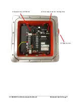
Two fuses, F1 and F2, are each mounted within fuse holders on the Terminal Output PC Board,
located directly under TB1.
•
F1 is used for all power configurations.
•
F2 is used only in 220 / 230 V AC applications.
Note:
The factory installed F2 bypass jumper J1, is hardwired for 110 V AC and
24 V DC systems. Refer to
Appendix A for Power and Fuse requirements
.
4.3.2
Heater
Two fuses, F3 and F4, are each mounted within fuse holders on the Terminal Output PC Board
located near the Heater connector SKT1.
•
F3 is used for all power configurations.
•
F4 is used only in 220 / 230 V AC applications.
Note:
The factory installed F2 bypass jumper J2, is hardwired for 110 V AC and
24 V DC systems. Refer to A
ppendix A for power and fuse requirements
and
Appendix E, drawing 613-816, Service Connections
.
4.4
Connection for mA Output
The mA current loop is a self-powered output for recorders or controllers requiring current loop
feedback. The QUASAR M8100-EXP supplies its own 4 … 20mA current to a load. The 4 … 20mA
output is isolated from the Power ground. Loads up to a maximum of 400 ohms may be
connected in SERIES. Once connected, voltage measured between mA outputs and Chassis GND
(common mode) should not to exceed 20 V DC.
A shield is recommended, however do not connect the shield to the instrument’s GND, connect
it only to the Chassis GND.
Caution:
Refer to
Chapter 10, Safety Assurances and Precautions
before
connecting the 4 … 20mA loop to the terminal.
Connect the mA lines to the corresponding (MA-) and (MA+) outputs on TB2.
•
Positive mA to mA+
•
Negative mA to mA-


