Table 3. Link/activity LED (Continued)
LED State
Description
Green
100 Mbit/s link established
Green, flickering
100 Mbit/s activity
Yellow
10 Mbit/s link established
Yellow, flickering
10 Mbit/s activity
Table 4. RJ-45 Ethernet pinout
Pin
Description
1
TD+
2
TX-
3
RX+
6
RX-
4, 5, 7, 8
Normally left unused; to ensure signal integrity, these pins are tied
together and terminated to PE via a filter circuit in the module.
Housing
Cable shield
CONFIGURING PROCESS CONTROL SOFTWARE
The Electronic Description Sheet (EDS) file contains information about the capabilities of the unit,
which can be used to configure the process control software. Download the current EDS file from the
AE website
http://www.advanced-energy.com/en/Anybus_modules_ThyroPX.html
Install the EDS file in the process control software.
CONFIGURING WITH THYRO-TOOL PRO PC
SOFTWARE
You can configure the Thyro-PX power controller using either the Thyro-Tool Pro PC software or the
Thyro
‑
Touch display.
To configure the unit, you will:
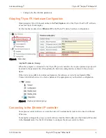
• Adapt the Thyro-PX hardware configuration
If required, you can also:
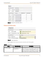
• Select the configuration
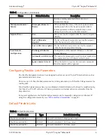
• Configure the diagnostics
Advanced Energy
®
Thyro-PX
™
Anybus
®
Ethernet IP
57010163-00A
Thyro-PX
™
Anybus
®
Ethernet IP
3


