20
3. OPERATION
3.1 CONFIGURATION SWITCH S1
A 4-pole DIP switch is situated at the front behind the hood. The indi-
vidual switches are marked from 1-4 starting from the bottom and must
be set before operation. They are only read in once when switched on
(mains recovery). For safety reasons further operation is carried out
with the hood closed.
S1-
1
2
Operating mode
0
0
1:1 operation, nom. Oper. mode (default setting)
1
0
1:2 operation
0
1
1:3 operation
1
1
1:5 operation
For operations where initially no nominal load is possible (e.g.drying)
reduced power can be controlled by Thyro-S independently.
With 1:2 operation each 2. cycle is switched, with 1:3 and 1:5 operation
half cycles are switched with alternating polarity so that while switched
on the load is supplied with d.c.-free energy.
S1-
3 Function
0 default
1 Thyro-Tool Family mode
Using the Thyro-Tool Family mode, all parameters can be configured
by software.
The following table is valid for dip-switch 4:
S1-
4 Function
0 default (resistive load)
1 resistive - inductive load (with phase angle of 1st half wave)
By switch S1-4, the Thyro-S can be adjusted to resistive – inductive
loads. This can be realized by phase angle of 1st half wave. If the
switch is closed, the value for phase angle of 1st half wave (short AN1)
can be adjusted by Thyro-Tool Family. The default value is 60°.
Summary of Contents for Thyro-S 1S H 1 Series
Page 2: ...2...
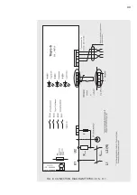
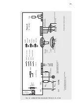
Page 35: ...33 FIG 8 CONECTION DIAGRAM THYRO S 1S H 1...
Page 36: ...34 FIG 9 CONNECTING DIAGRAM 2X THYRO S 1S H 1...
Page 37: ...35 FIG 10 CONNECTING DIAGRAM THYRO S 1S H RL1...
Page 38: ...36 FIG 11 CONNECTING DIAGRAM 2X THYRO S 1S H RL1...
Page 44: ...42 11 DIMENSIONAL DRAWINGS THYRO S 1S 16H 30H THYRO S 1S 45H 60H...
Page 45: ...43 THYRO S 1S 100H THYRO S 1S 130H 170H...
Page 46: ...44 THYRO S 1S 280H...
Page 50: ......
Page 51: ......
Page 52: ......
Page 54: ......


