Version 15.0
AF-5000 Series Pilot Guide
26
Altitude
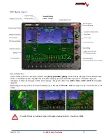
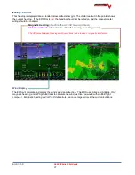
The altitude tape gives a visual representation of altitude. The digital readout points to
current altitude, thousands of feet are displayed using large numbers while hundreds of
feet are displayed
using smaller numbers. The green chevrons are located at 1000’
intervals for IFR cruising altitudes and the white chevrons are located at 500’ indicating
VFR cruising altitudes. Above the tape are two boxes showing the value of the two
altitude bugs. The main ALT bug is for the Flight Director altitude pre-select. It's altitude
is shown in the upper box. The lower box displays altitude for the MIN ALT bug which is
used to program a DH/MDA for an IFR approach.
Barometric Pressure/Altitude
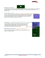
The current barometer setting is displayed in the box below the altitude tape. The
value is shown in either inches of Mercury or millibars. The current barometer setting
can be adjusted by turning the joystick anytime the
BARO
function is active. If
BARO
is not active, press the button above the joystick to make
BARO
the active
function. The current field elevation is stored in memory so that the altitude should be
correct after a power cycle.
Airspeed
The airspeed is displayed on the left side of the screen using an analog 4 color tape
and digital readout. The airspeed range marks can be adjusted in Instrument
Calibration under Airspeed. The airspeed units are displayed in both the upper
Indicated Airspeed box and the lower True Airspeed box. A barber pole style hash will
automatically show above Vne. GPS derived Ground Speed is also given below the
TAS readout.
Horizon Roll and Pitch
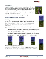
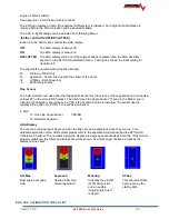
The horizon (roll and pitch) works the same way that a
traditional artificial horizon works. The white zero pitch line
stays parallel to the actual horizon regardless of the aircrafts
pitch and roll configuration. The zero pitch line is not always
on the horizon. If the display is showing terrain above the
zero-pitch line, the aircraft is below the upcoming terrain.
The parallel lines above and below the horizon line are the
pitch indicator lines. Similarly the arrow rotating around the
roll indicator gives visual representation of the current roll
angle. Each mark represents 10 degrees of roll with longer
marks at 0, 30, 45, and 60. The pitch line can be adjusted
for level flight from the main EFIS page by pressing the
following buttons
[SET] -> [AHRS] ->
[PTCH ADJ]
or
[EFIS]
-> [PTCH ADJ].
The joystick is then used to adjust for level
flight pitch.
Summary of Contents for AF-5400
Page 58: ...Version 15 0 AF 5000 Series Pilot Guide 58 Flowchart Pitch Axis IAS Hold Procedure...
Page 60: ...Version 15 0 AF 5000 Series Pilot Guide 60 Altitude Capture Procedure Part 1 of 2 Part 2 of 2...
Page 62: ...Version 15 0 AF 5000 Series Pilot Guide 62 Autopilot Settings Defaults...
Page 73: ...Version 15 0 AF 5000 Series Pilot Guide 73 FREQ Tab RCNT Tab...
Page 88: ...Version 15 0 AF 5000 Series Pilot Guide 88 VFR Sectional Full Screen Mode Split Screen Mode...
Page 89: ...Version 15 0 AF 5000 Series Pilot Guide 89 IFR Low Altitude Chart Airport Diagrams...

